
Apparatus and method for forming an antipollution device housing

a technology of anti-pollution device and housing, which is applied in the direction of mechanical apparatus, engine components, machines/engines, etc., can solve the problems of affecting the environment, affecting the sanitary conditions of the housing, so as to achieve the effect of resisting deformation of the formed chamber

Active Publication Date: 2010-11-25
GWS TUBE FORMING SOLUTIONS
View PDF30 Cites 0 Cited by
  • Summary
  • Abstract
  • Description
  • Claims
  • Application Information

AI Technical Summary

Benefits of technology

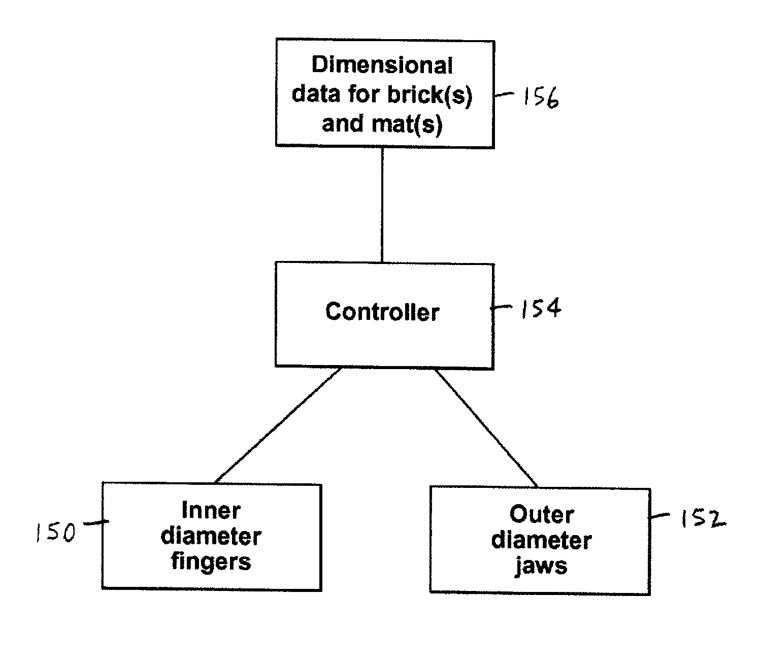
[0027]In its broad aspect, the invention provides an apparatus for forming a workpiece with an inner surface and an opposed outer surface into a housing of an antipollution device for treating exhaust in which one or more preselected catalyst-bearing bricks are positionable, and in which one or more mats are positionable between the brick(s) and the housing to support the brick(s). At least part of the inner surface defines an initial chamber in the workpiece with one or more initial dimensions. The apparatus includes a first set of members for engaging the inner surface and a second set of members for engaging the outer surface. The apparatus also includes a controller adapted to receive dimensional data for the brick(s) and the mat(s) and, based on the dimensional data, to determine one or more calculated dimensions at least partially defining a formed chamber in a main portion of the housing. The calculated dimension(s) is sized for compressing the mat to the preselected density when brick(s) is positioned in the formed chamber and when mat(s) is positioned between the brick(s) and the housing. Also, the controller is adapted to control a selected one of the first and second sets of members for engaging the workpiece to change the initial dimension(s) to the calculated dimension(s), for compressing the mat(s) to the preselected density when the brick(s) and the mat(s) are positioned in the formed chamber of the housing. The controller is additionally adapted for controlling the first and second sets of members to form one or more end portions of the housing with at least one preselected dimension thereof having a predetermined relation to the calculated dimension(s). In addition, the controller is adapted for controlling the first and second sets of members to form at least one transition portion of the housing connecting an end portion with the main portion of the housing substantially without deformation of the formed chamber.
[0031]In yet another of its aspects, the invention provides a method of manufacturing an antipollution device with a housing having a formed chamber in which one or more catalyst-bearing bricks are supported by one or more mats. The method includes, first, providing dimensional data for the brick(s) and the mat(s), and second, providing a workpiece with an inner surface and an opposed outer surface thereof, at least part of the inner surface defining an initial chamber with one or more initial dimensions. Next, one or more calculated dimensions of the main portion of the housing based on the dimensional data is calculated. The calculated dimensions at least partially defining the formed chamber so that the mat is compressed between the brick(s) and the housing to a preselected density when the brick(s) and the mat(s) are positioned in the formed chamber within the main portion. In the next step, a selected one of first and second sets of members is engaged with the workpiece to change the initial dimension(s) to the calculated dimension(s). Then, an end portion of the housing is formed with one or more preselected dimensions thereof having predetermined relations to the dimension(s). Next, a transition portion connecting the end portion with the main portion of the housing is formed substantially simultaneously, at least a part of the main portion proximal to the transition portion is engaged with the other of said first and second sets of members, for resisting deformation of the formed chamber.

Problems solved by technology

In the prior art, manufacturing the housings of these antipollution devices usually involves time-consuming (and therefore relatively costly) steps taken to address certain problems.
Diesel engines also produce a large volume of particulate (i.e., soot) which is also extremely detrimental to the environment.
Similarly, because of the performance requirements and system constraints, the housing's main portion may not be symmetric with respect to its center.
A number of problems have arisen in connection with the known methods of manufacturing antipollution devices.
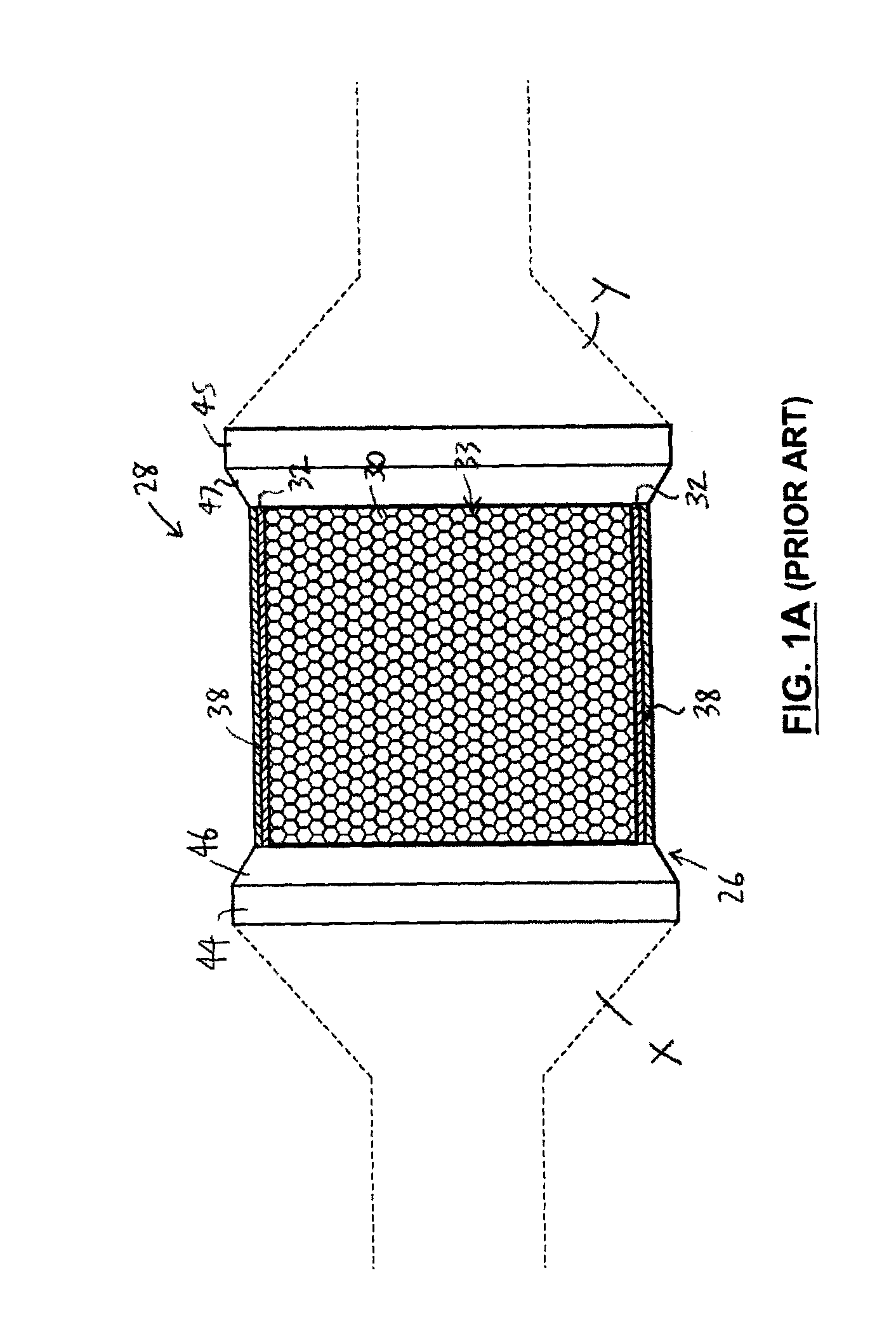
The methods of the prior art have resulted in many failures due to inaccurate forming of the main portion 38, the end portion 44, 45, and the transition portions 46,47 in relation to the dimensions of the specific mat and the brick(s) which are assembled within the particular housing.
For instance, if the housing is incorrectly formed too large, then the brick / mat subassembly 33 slides in relation to the housing 26, resulting in damage to the brick 30 and / or mat 32 and, as a direct consequence, the immediate failure of the antipollution device when it is used.
On the other hand, if the housing 26 is sized too small or too tight, the antipollution device either cannot be assembled or the brick / mat subassembly 33 is damaged during the assembly process, which typically results in impaired performance or failure of the antipollution device.
If a transition portion is too abrupt (i.e., too steep), depending on the circumstances, such too short transition portion may cause different problems.
Also, as another example, where a previously stuffed housing is reduced to GBD (described below) and the end portions are then further reduced to a smaller size, the transition portion will become too steep and natural material flow may result in the inner wall surface of the housing touching and potentially chipping (breaking) the edges of the brick, if the transition portion is not supported during forming.
As noted above, however, there is no prior art method or apparatus for properly forming the main portion and the end portions, and the transition portions relative to the formed main portion.
However, because the tolerance is relatively fine, even a small deviation from the required dimensions of the housing can result in an unacceptable assembly.
Accordingly, because the prior art method of making the antipollution device can easily result in an unacceptable assembly, significant efforts are made in the prior art to form each housing with the correct dimensions for each individual brick / mat subassembly, resulting in significant manufacturing costs.
Using this many machines involves a relatively high unit expense and also requires time to be spent in the manufacturing process moving the workpiece between machines.
Because such methods are based on approximations, however, the transition portions frequently are improperly formed, resulting in housings rejected due to failure to meet quality control standards or early failure of antipollution devices including the housings formed using such methods.

Method used


Image

  • Apparatus and method for forming an antipollution device housing
  • Apparatus and method for forming an antipollution device housing
  • Apparatus and method for forming an antipollution device housing

Examples


Embodiment Construction

[0084]To simplify the description, the numerals used previously in describing FIG. 1A will be used again, except that each such numeral is raised by 100 (or multiples thereof, as the case may be), where the parts described correspond to parts already described.

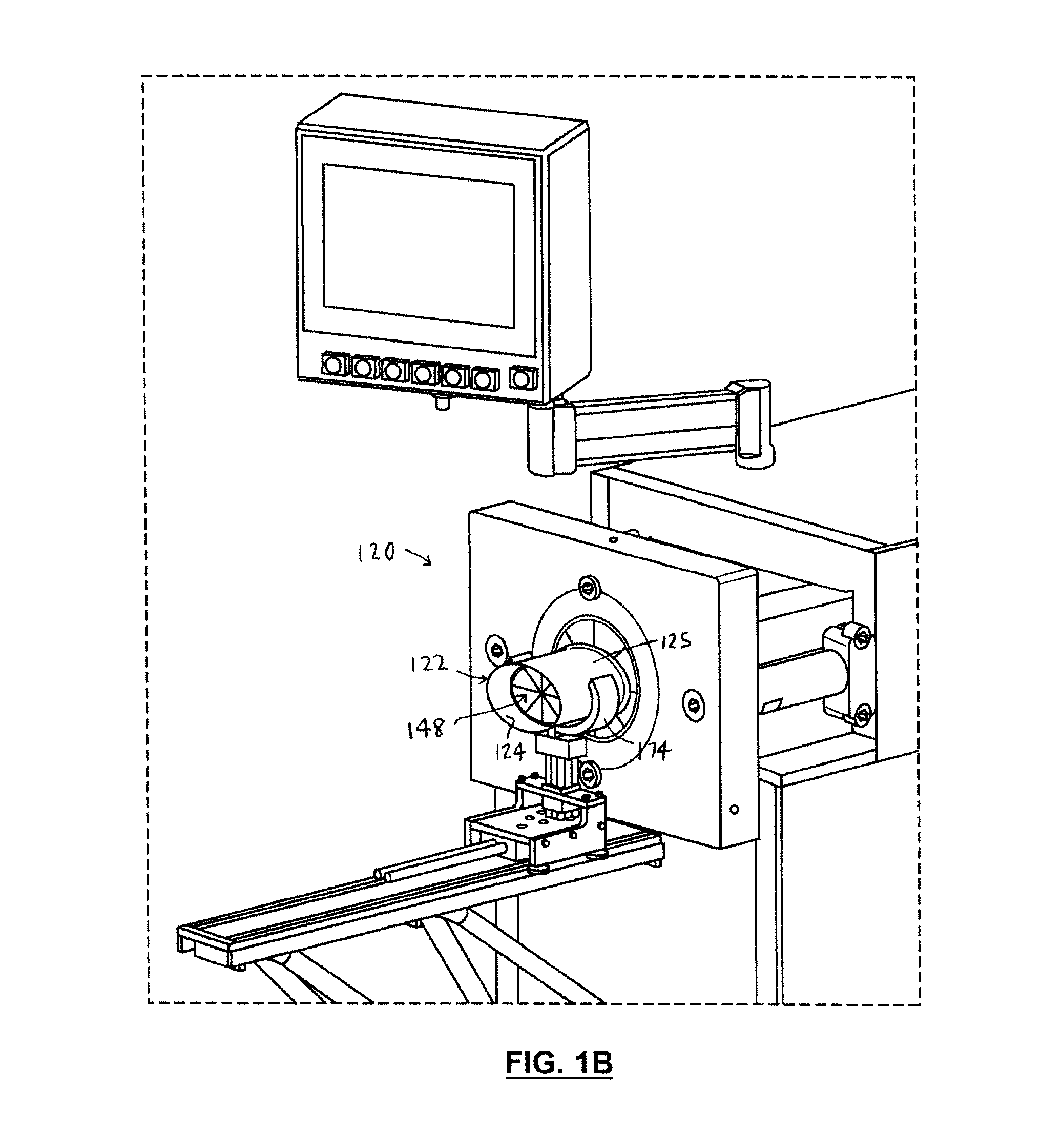
[0085]Reference is first made to FIGS. 1B-8B to describe an embodiment of an apparatus 120 of the invention. The apparatus 120 (FIG. 1B) is for forming a workpiece 122 with one or more inner surfaces 124 and an opposed outer surface 125 into a hollow housing 126 (FIG. 1D) of an antipollution device 128 for treating exhaust in which one or more preselected catalyst-bearing bricks 130 is positionable, and in which one or more mats 132 are also positionable between the brick 132 and the housing 126 to support the brick 132 (FIG. 1C). At least part 127 of the inner surface 124 defines an initial chamber 136 in the workpiece 122 with an initial dimension 137 (FIG. 2A). (For clarity of illustration, the workpiece is illustrated twic...


PUM

PropertyMeasurementUnit
densityaaaaaaaaaa
dimensionaaaaaaaaaa
initial dimensionaaaaaaaaaa

Abstract

An apparatus and a method for manufacturing a housing of an antipollution device including one or more bricks supported by one or more mats therein. One or more main portions are formed, the main portion of the housing defining a formed chamber in which the brick(s) compress the mat(s) between the brick(s) and the main portion to a predetermined density. One or more end portions are formed, for connection of the antipollution device in an exhaust system. When one or more transition portions are formed to connect the main portion(s) and the end portion(s), the main portion(s) is engaged by the apparatus to resist deformation of the formed chamber.

Description

FIELD OF THE INVENTION[0001]This invention is related to an apparatus and a method for forming an antipollution device housing.BACKGROUND OF THE INVENTION[0002]Various antipollution devices adapted to be included in automotive exhaust systems are known. Two common examples are the catalytic converter and the diesel particulate filter (“DPF”). Such known antipollution devices typically include housings in which certain components are positioned. In the prior art, manufacturing the housings of these antipollution devices usually involves time-consuming (and therefore relatively costly) steps taken to address certain problems.[0003]Catalytic converters are used for processing exhaust gases from a spark ignition engine powered by a fuel (e.g., gasoline, liquified petroleum gas, various blends of E85 and gasoline, and compressed natural gas) and from compression ignition (diesel) engines, to reduce or eliminate certain harmful gases (i.e., pollutants) in the exhaust gases. In general, th...

Claims


Application Information

Patent Timeline
Patent Type & Authority Applications(United States)
IPC IPC(8): F01N3/00B23P19/00B23P11/00F01N13/18
CPCB23P2700/03F01N3/2853F01N13/18F01N3/2839F01N13/1872Y10T29/49345F01N2350/04F01N2450/02F01N2450/20Y10T29/53Y10T29/49826F01N2350/02Y02T10/12
Inventor SOJAK, RICHARDBAILEY, CLIFFORDRAMANDT, JAMESDEVINE, GUY
Owner GWS TUBE FORMING SOLUTIONS
Learn More