
Automated Inspection System and Method for Nondestructive Inspection of a Workpiece Using Induction Thermography

a technology of induction thermography and inspection system, which is applied in the direction of mechanical roughness/irregularity measurement, instruments, nuclear elements, etc., can solve the problems of high-stressed components whose structural integrity is compromised, substantial damage to the machinery involved, and substantial costs and delays in view of the relatively large number of components

Inactive Publication Date: 2010-11-18
SIEMENS ENERGY INC
View PDF26 Cites 18 Cited by
  • Summary
  • Abstract
  • Description
  • Claims
  • Application Information

AI Technical Summary

Problems solved by technology

Operation of large rotating machinery can produce substantial mechanical forces that can result in highly-stressed components whose structural integrity needs to be evaluated on periodic basis.
In the event of a structural malfunction of any such component, substantial damage could occur to the machinery involved, e.g., the generator and / or a turbine connected to the generator.
This inspection technique has proven to be reliable but suffers from at least the following drawbacks: The coating has to be removed from the components before inspection and the reusable components have to be recoated after the inspection, which leads to substantial costs and delays in view of the relatively large number of components that may be involved.

Method used


Image

  • Automated Inspection System and Method for Nondestructive Inspection of a Workpiece Using Induction Thermography
  • Automated Inspection System and Method for Nondestructive Inspection of a Workpiece Using Induction Thermography
  • Automated Inspection System and Method for Nondestructive Inspection of a Workpiece Using Induction Thermography

Examples


Embodiment Construction

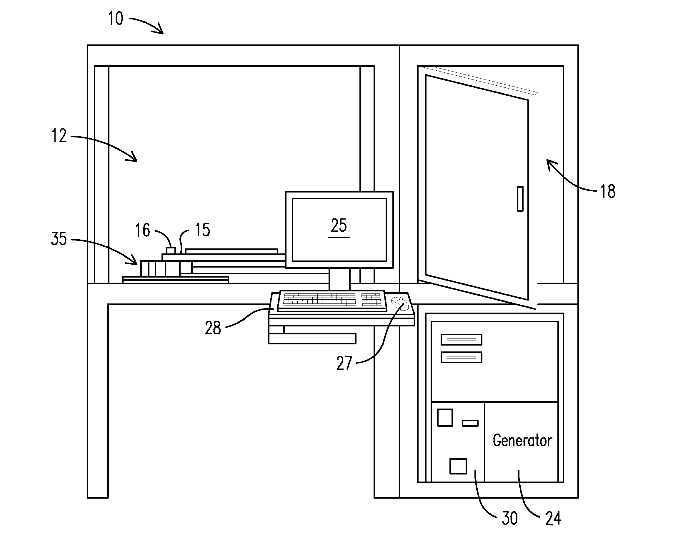
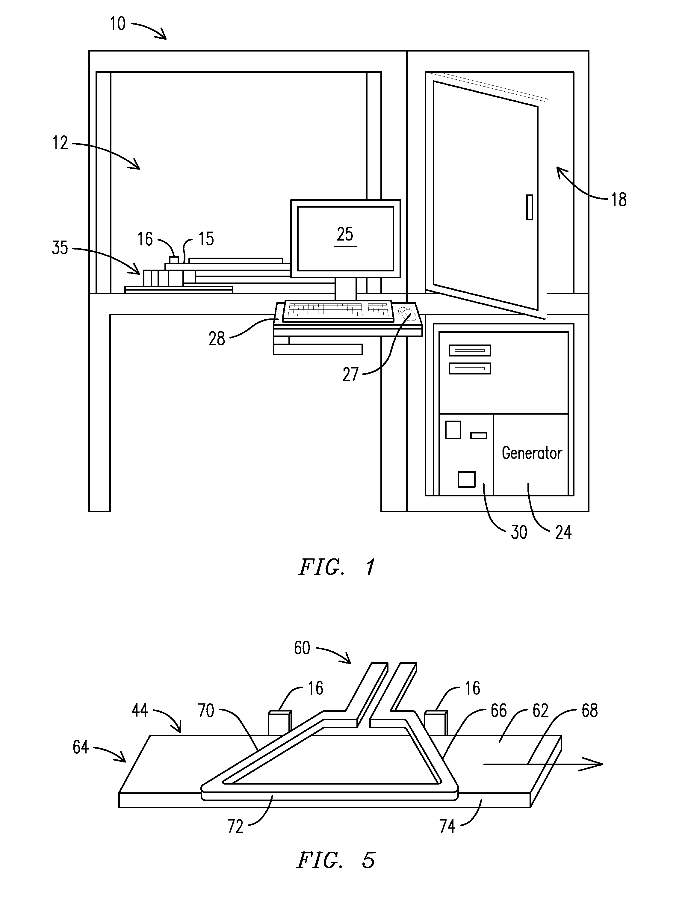
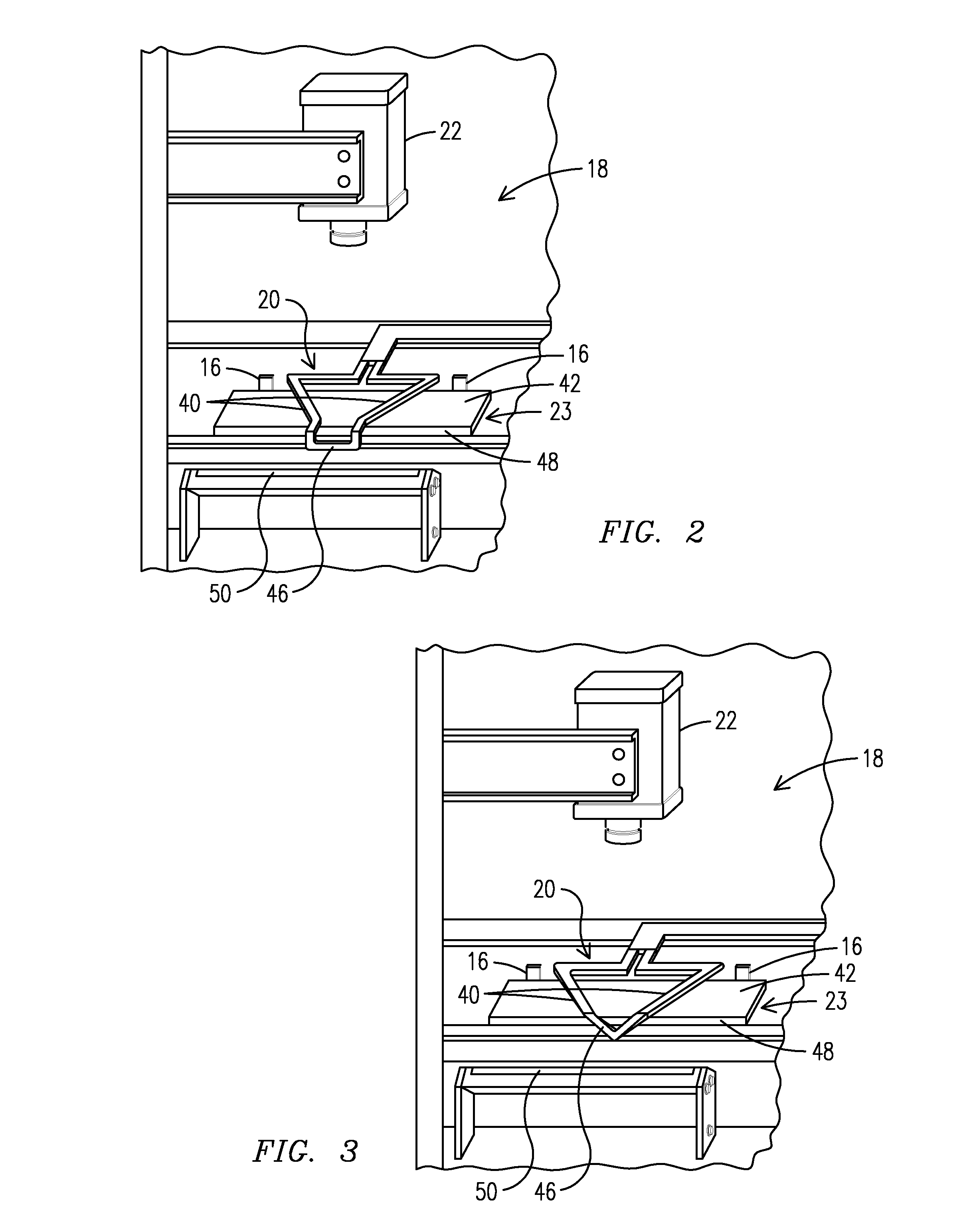
[0012]FIG. 1 is a schematic of an automated inspection system 10 embodying aspects of the present invention. Inspection system 10 is arranged for nondestructive inspection and evaluation (NDE) of components based on induction thermography. As will be appreciated by one skilled in the art, in induction thermography an alternating current (e.g., excitation current) in an inductor coil, induces a current in an electrically-conducting material—a workpiece or component to be inspected, such as rotor wedges or other components of rotating machinery, or any component exposed to relatively high mechanical stresses—placed proximate to the inductor coil. If a structural defect (e.g., a crack or other subsurface discontinuity) is present in the workpiece, the current flow is locally disrupted, resulting in an altered current density distribution, and therefore in an altered heating pattern around the area of the defect.

[0013]A penetration depth s of the induced current (e.g., skin effect) may ...


PUM

PropertyMeasurementUnit
electrical poweraaaaaaaaaa
electrically-conductiveaaaaaaaaaa
thermal responseaaaaaaaaaa

Abstract

Automated inspection system and method are provided for nondestructive inspection and evaluation of an electrically-conductive workpiece based on induction thermography. A movable carriage (15) may be arranged to translate the workpiece in an inspection location (18). An induction coil 20 is disposed at the inspection location. The induction coil is responsive to an excitation current to induce a flow of electrical current in a region of interest of the workpiece. A thermographic camera (22) is disposed at the inspection location. The thermographic camera is arranged to capture data indicative of a thermal response resulting from the flow of electrical current. A computer system (30) is configured to process the data from the thermographic camera to generate an indication of a presence of a discontinuity (e.g., a subsurface crack) in the workpiece.

Description

RELATED APPLICATIONS[0001]This application claims benefit of U.S. provisional patent application No. 61 / 178,770, and U.S. provisional patent application No. 61 / 178,783, each filed on May 15, 2009 and respectively incorporated by reference herein in their entirety.FIELD OF THE INVENTION[0002]The present invention is generally related to nondestructive inspection and evaluation (NDE) of components, and, more particularly, to an automated inspection system and method for NDE of components based on induction thermography.BACKGROUND OF THE INVENTION[0003]Operation of large rotating machinery can produce substantial mechanical forces that can result in highly-stressed components whose structural integrity needs to be evaluated on periodic basis. For example, electric power generators, as may be used in a power generation plant, include a rotor arranged with a plurality of coils. To lock the coils into position, rotor wedges may be used. The rotor wedges may be constructed from non-magneti...

Claims


Application Information

Patent Timeline
Patent Type & Authority Applications(United States)
IPC IPC(8): G01N25/72G06F19/00
CPCG01N25/72
Inventor VRANA, JOHANNES L.MOOSHOFER, HUBERTGOLDAMMER, MATTHIASROTHENFUSSER, MAXHEINE, WOLFGANG
Owner SIEMENS ENERGY INC
Learn More