
Forward Scanning OCT Endoscope

a technology of optical coherence tomography and endoscope, which is applied in the direction of tomography diagnosis, sensors, diagnostics, etc., can solve the problems of affecting the accuracy of the detection results, the interference signal, and the difficulty in achieving the effect of achieving accurate detection results, and achieves compact and narrow design

Inactive Publication Date: 2010-11-18
MEDIZINISCHES LASERZENTRUM LUEBECK GMBH
View PDF4 Cites 55 Cited by
  • Summary
  • Abstract
  • Description
  • Claims
  • Application Information

AI Technical Summary

Benefits of technology

[0019]The object of the invention is to suggest an applicator for an OCT system that has a particularly compact and narrow design and is therefor...

Problems solved by technology

The realization and control of such phase modulators is technically complex and relatively expensive.
This results in constructive or destructive interference for any desired fixed distance z of the planes depending on which of the irradiated wavelengths λ are observed.
Every movement and / or twisting of the fiber, but also temperature, variations or mechanical stress, influence the travel time of the sample light and lead to interference signals relative to a reference branch that is not exposed to these factors when the sample and reference lights are superposed.
However this means that the reference mirror, too, has to be accommodated in the applicator.
However it has the disadvantage that the OCT measurement can only succeed to the side in the tissue immediately neighboring onto the endoscope.
Although it is unproblematic to design a sufficiently large focal length of the focusing optics, but providing the beam splitter and the reference mirror in or at the forwardly facing exit window is not a favorable measure since sample and reference branch lengths of the interferometer will then differ by too much.
If however this laterally facing reference branch requires a length of a few millimeters either the setup will become very complicated or the distal end of the endoscope will not become very narrow.

Method used


Image

  • Forward Scanning OCT Endoscope
  • Forward Scanning OCT Endoscope

Examples


Embodiment Construction

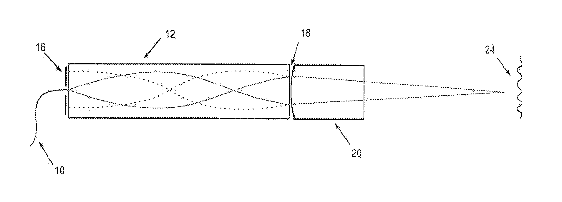
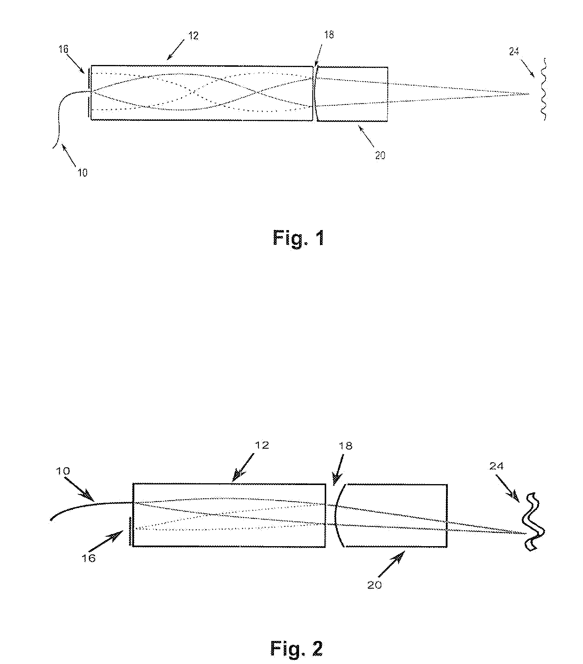
[0031]The invention in principle takes advantage of the image-conducting attributes of GRIN optics so as to realize the reference branch using simple means. Here in principle two variations are possible, depending on whether an axially symmetric light-guiding arrangement is to be realized or not.

[0032]FIG. 1 represents the symmetric case. Here N has to be an odd number, for example N is set=5. The optical fiber 10 is connected (usually glued) to the inventive GRIN device 12 in such a way that the light leaves the fiber precisely at the center of the proximal flat side along the axis of symmetry of the GRIN device. The proximal flat side is completely mirrored with the exception of the surroundings of the fiber end, i. e. a highly reflective coating 16 that is interrupted at the center is applied to the proximal flat side. The continuous lines indicate the beam path of the light cone that starts from the fiber end and at first leads to the distal flat side of the GRIN device where th...


PUM


Abstract

An apparatus for optical coherence tomography has a broadband light source with a short coherence length, an optical fiber that guides the light from the light source to a focusing optics, and a graded-index optics arranged between the optical fiber and the focusing optics with two opposite parallel flat sides, that is contacted on its first flat side by the optical fiber forming an irradiation point guiding light to the graded-index optics and having a pitch of N / 8, N being a natural number that cannot be divided by 4. A first structure for light reflection is arranged on the first flat side of the graded-index optics adjacent to the irradiation point, and a second structure for beam splitting is arranged on the second flat side of the graded-index optics. The focusing optics are designed for focusing the light transmitted by the second structure essentially at right angles to the flat sides of the graded-index optics.

Description

BACKGROUND OF THE INVENTION[0001]The invention relates to an apparatus for Optical Coherence Tomography (OCT) using an applicator that is designed in the fashion of an endoscope for introduction into cavities, in particular body cavities of a living human being or animal.[0002]The OCT method is presently state of the art in medical diagnostics. Here broadband light with a short coherence length from a suitable light source (e. g. from a superluminescent diode) is at first subdivided into a sample and a reference light beam, and then the sample beam is directed at the object to measured (e. g. living tissue such as epidermis, retina) and reflected back by it into different depths. In contrast, the reference light is in principle reflected from a reference mirror and guided such that it has passed approximately the same optical path length as the sample light when it is finally rejoined with the returning sample light in an evaluation unit and superposed thereon. The signal of interes...

Claims


Application Information

Patent Timeline
IPC IPC(8): A61B1/07
CPCA61B5/0073G01N21/4795G01B9/02091G01B9/0205G01B9/02057A61B5/0066
Inventor LANKENAU, EVABONIN, TIMHUETTMANN, GEREON
Owner MEDIZINISCHES LASERZENTRUM LUEBECK GMBH
Learn More