
Image pickup apparatus and optical-axis control method

a technology of image pickup and optical axis control, which is applied in the direction of television systems, instruments, printing, etc., can solve the problems of difficult to reduce the resolution cannot be enhanced in accordance with the subject distance, and the size and thickness of the image pickup apparatus are increased. , to achieve the effect of high image-quality image pickup apparatus and simple manner

Inactive Publication Date: 2010-11-18
SHARP KK
View PDF27 Cites 128 Cited by
  • Summary
  • Abstract
  • Description
  • Claims
  • Application Information

AI Technical Summary

Benefits of technology

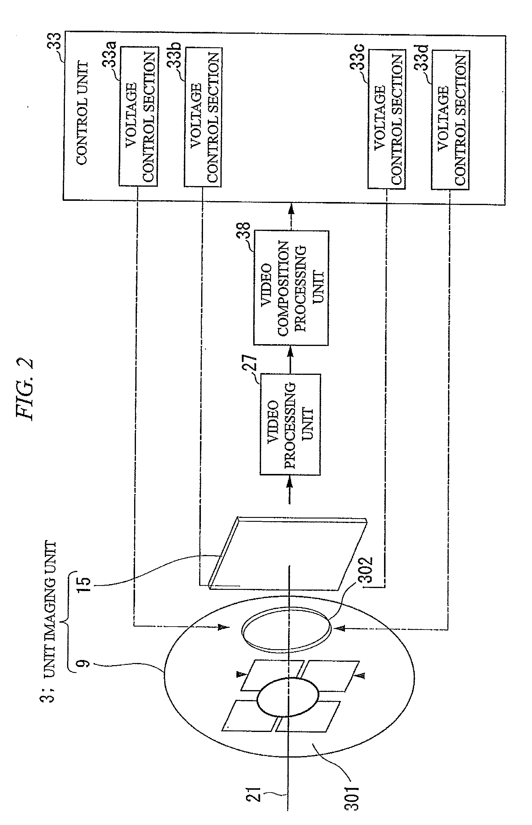
[0030]According to the present invention, a plurality of imaging devices; a plurality of solid lenses that form images of the imaging devices; and a plurality of optical-axis control units that control the direction of optical axes of light incident to the imaging devices are included. Accordingly, the adjustment of the relative position of the imaging optical system and the imaging device can be performed in an easy manner without requiring a manual operation. Therefore there is an advantage in that a high image-quality image pickup apparatus can be realized. In particular, the optical axis of incident light can be controlled to be set to an arbitrary position on the surface of the imaging device. Accordingly, a high image-quality image pickup apparatus capable of performing the positional adjustment between the optical system and the imaging device in a simple manner can be realized. In addition, the direction of the optical axis is controlled based on the relative positions of an imaging target and a plurality of optical-axis control units. Accordingly, the optical axis can be set to an arbitrary position on the surface of the imaging device, whereby an image pickup apparatus having a wide range of focal adjustment can be realized.

Problems solved by technology

Accordingly, the size of the image pickup apparatus is increased, and there is a problem in that it is difficult to decrease the size and the thickness thereof.
Accordingly, a problem in that the resolution cannot be enhanced in accordance with the subject distance is solved.

Method used


Image

  • Image pickup apparatus and optical-axis control method
  • Image pickup apparatus and optical-axis control method
  • Image pickup apparatus and optical-axis control method

Examples


first embodiment

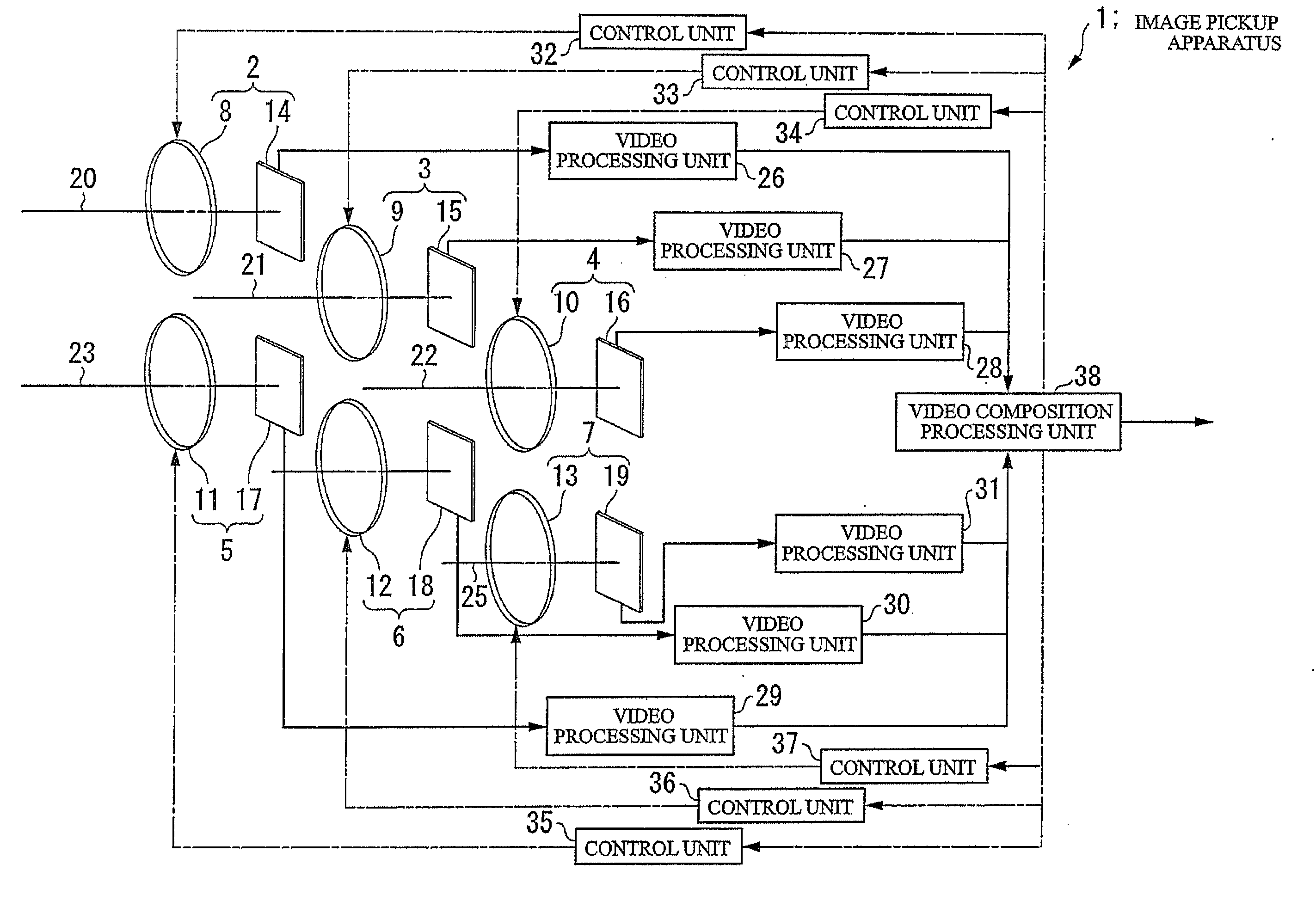
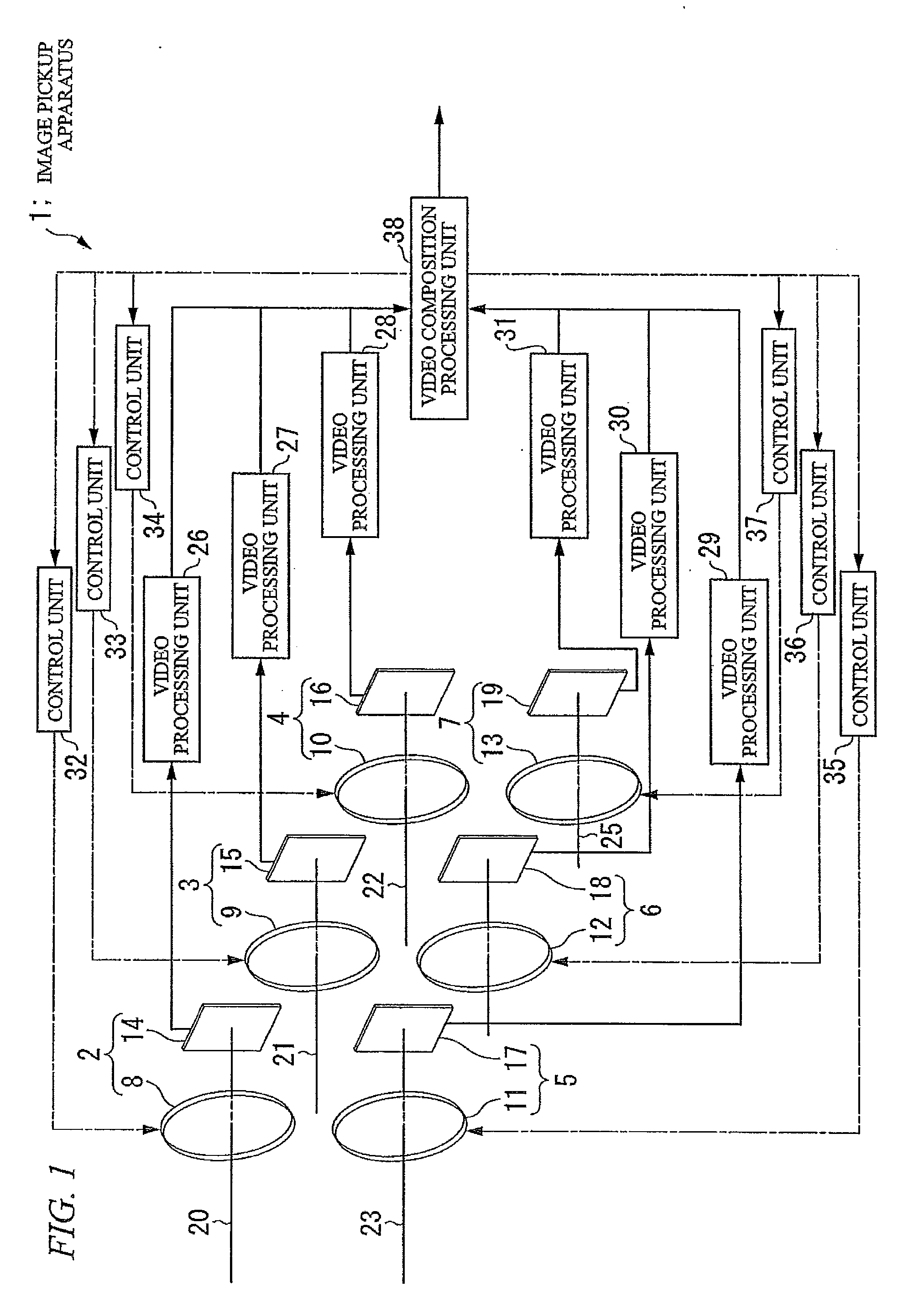
[0087]Hereinafter, embodiments of the present invention will be described in detail with reference to the accompanying drawings. FIG. 1 is a functional block diagram showing the entire configuration of an image pickup apparatus according to the present invention. The image pickup apparatus 1 shown in FIG. 1 includes six systems of unit imaging units 2 to 7. The unit imaging unit2 is configured by an imaging lens 8 and an imaging device 14. Similarly, the unit imaging unit 3 is configured by an imaging lens 9 and an imaging device 15, the unit imaging unit 4 is configured by an imaging lens 10 and an imaging device 16, the unit imaging unit 5 is configured by an imaging lens 11 and an imaging device 17, the unit imaging unit 6 is configured by an imaging lens 12 and an imaging device 18, and the unit imaging unit 7 is configured by an imaging lens 13 and an imaging device 19. Each imaging lens 8 to 13 images light transmitted from a photographing target on the corresponding imaging d...

seventh embodiment

[0201]Next, a seventh embodiment will be described with reference to FIG. 36. In the above-described embodiments, a configuration in which all the imaging devices having the same specifications are used, and the pixel pitches of the imaging devices 14 to 19 shown in FIG. 1 are the same. Accordingly, the state shown in the upper diagram of FIG. 34B is formed, the frequency at which the phases of the pixels coincide with each other increases, and there is a case where high resolution cannot be implemented.

[0202]According to the seventh embodiment, imaging devices having different pixel pitches are used as the six imaging devices 14 to 19 shown in FIG. 1.

[0203]In FIG. 36, intersections of solid lines represent the pixels of the imaging device M, and intersections of dotted lines represent the pixels of the imaging device N. The value of pixel Puv needed for implementing high resolution can be acquired by performing a filter operation by using weighting coefficients according to the dis...


PUM


Abstract

In order to perform adjustment of relative positions between an optical system and imaging devices, a plurality of the imaging devices, a plurality of solid lenses that form images of the imaging devices, and a plurality of optical-axis control units that control the direction of optical axes of light incident to the imaging devices are included.

Description

TECHNICAL FIELD[0001]The present invention relates to an image pickup apparatus and an optical-axis control method.[0002]Priority is claimed on Japanese Patent Application No. 2008-003075, filed Jan. 10, 2008 and Japanese Patent Application No. 2008-180689, filed Jul. 10, 2008, the contents of which are incorporated herein by reference,BACKGROUND ART[0003]Recently, digital still cameras and digital video cameras (hereinafter, referred to as digital cameras) having high image quality have been widely used. In addition, developments for decreasing the size and the thickness of the digital camera have been made, and miniaturized digital cameras having high image quality have been built in mobile phone terminals and the like. An image pickup apparatus that is represented by a digital camera that includes an imaging device, an imaging optical system (lens optical system), an image processor, a buffer memory, a flash memory (card-type memory), an image monitor, and electronic circuits, me...

Claims


Application Information

Patent Timeline
Patent Type & Authority Applications(United States)
IPC IPC(8): G02B13/16G03B13/00H04N5/232
CPCG02B3/0056G02B3/14G02B7/365G02F1/1313G02F2001/294H04N5/349G03B15/00G03B2205/0007H04N5/2254H04N5/232G03B5/00G02F1/294H04N23/959H04N25/48
Inventor ITO, HIROSHIKITAGAWA, MAKOTOSHIMURA, TOMOYAARITA, SHINICHIINOUE, SATORUKATAKAME, HIROKAZUSAITO, SAKAESATO, SHUNICHI
Owner SHARP KK
Learn More