Device for transmitting motion for conveyor belts

Inactive Publication Date: 2010-11-11
ALIT
View PDF26 Cites 0 Cited by
  • Summary
  • Abstract
  • Description
  • Claims
  • Application Information

AI Technical Summary

Benefits of technology

[0019]The aim of the present invention is to provide a device for transmitting motion for conveyor belts that solves the problems and drawbacks revealed by known driving means and elongation recovery means.
[0020]Within this aim, an object of the present invention is to provide a device for transmitting motion that is cheaper, simpler to install and more industrializable than known types.
[0021]Another object of the present invention is to provide a motion transmission device that can be installed easily on known conveyor belts.
[0022]Another object of the present invention is to provide a device for transmitting motion that optimizes the motion of the belt, avoiding accumulations and / or tensions, tears, plastic deformations and anything that may lead to malfunctions of the belt.
[0024]Another object of the invention is to provide a device that allows not only uniformity and continuity in torque transmission but also safety of the integrity of the belt and of the driving means.

Problems solved by technology

The belt, which generally has a certain elasticity, being thus strained, elongates; moreover, such belt can elongate due to irregularities in the pitch of the gears or of the rings, due to temperature variations, due to wear of the chains or gears, and due to the production tolerances of its components and other similar drawbacks.
However, excessive elongation can cause the belt to break or undergo a plastic deformation that makes it defective and with problems in operation.
An excessive tensioning of the belt may further cause the displacement of the conveyed products from the correct conveyance position, with the risk of compromising the subsequent operations of the process (such as for example boxing, packaging and the like) to which such products are subjected.
Such elastic curves have a structure that is relatively complicated and expensive to provide.
The elastic curves in fact must be designed to size for each conveyor belt supporting frame and as such must also be produced in limited batches, with consequent substantial production costs.
These known recovery means, moreover, do not lend themselves to protecting the integrity of the belt in case of complete jamming of the belt, since the driving means, if they continued to operate, would cause the breakage of the belt or their own breakage.
These known recovery means generally have a bulky structure and limit the useful space for the product on the conveyor belt.

Method used


Image

  • Device for transmitting motion for conveyor belts
  • Device for transmitting motion for conveyor belts
  • Device for transmitting motion for conveyor belts

Examples


first embodiment

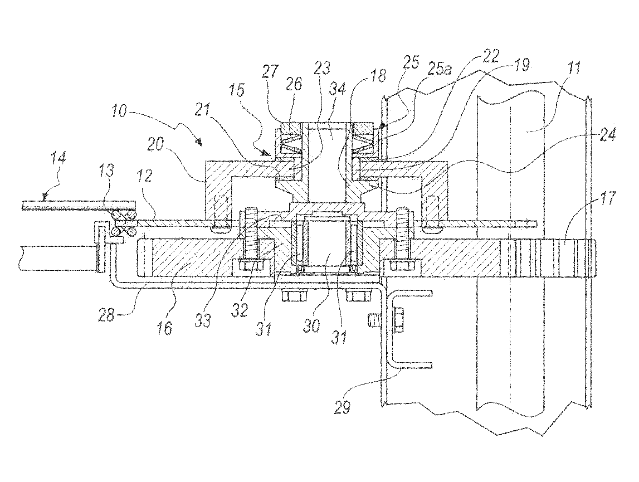
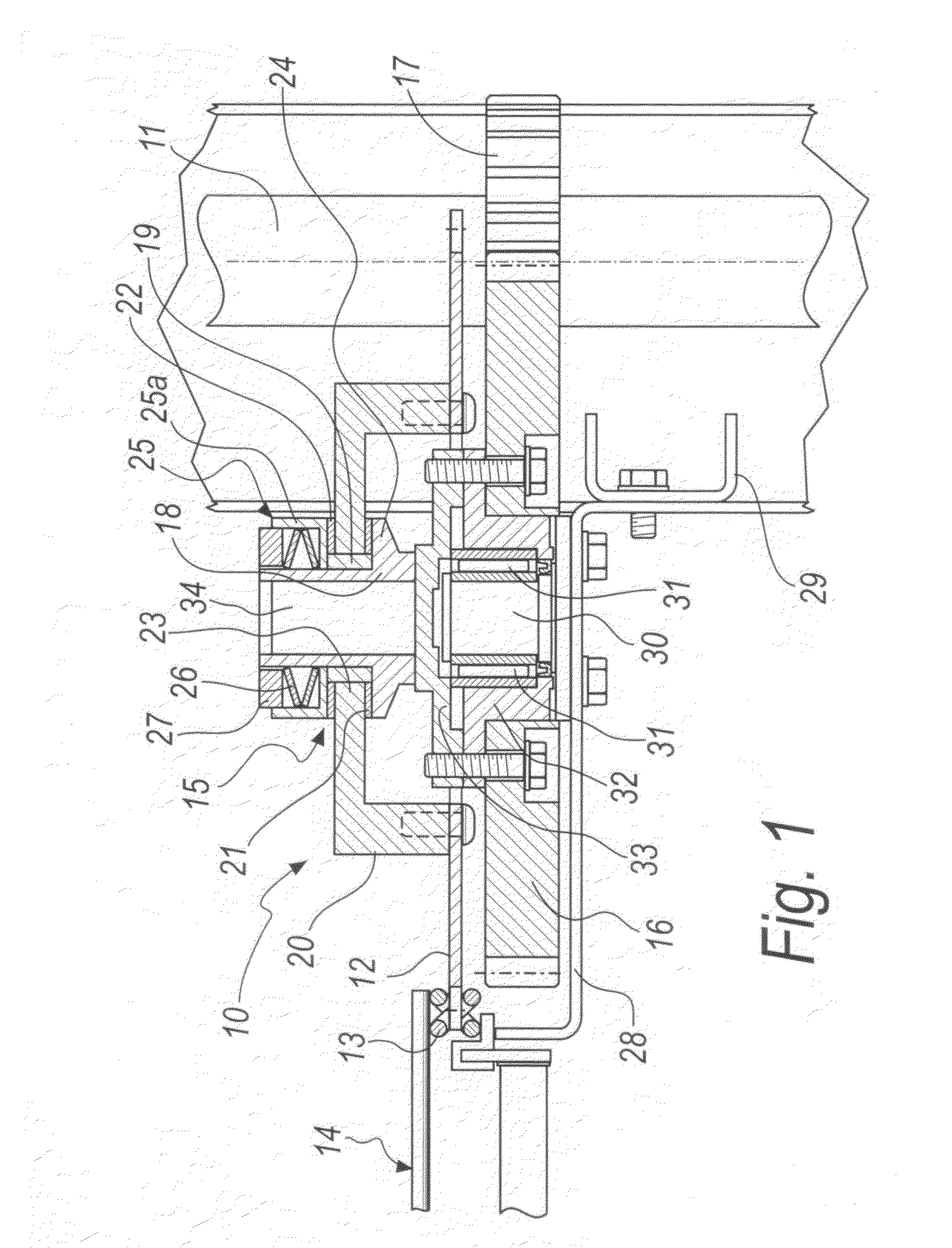
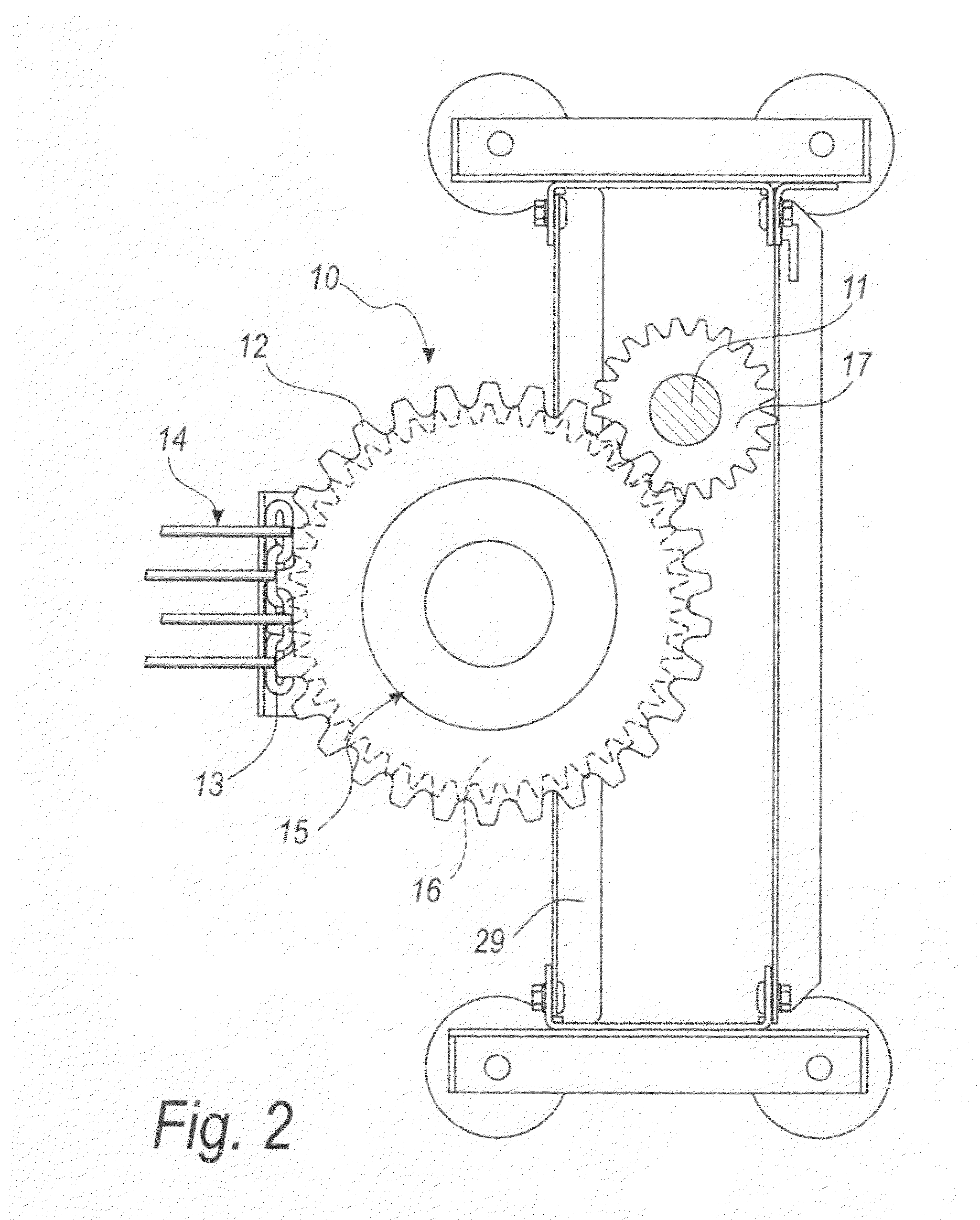
[0033]With reference to the figures, a device for transmitting motion for conveyor belts is generally designated by the reference numeral 10 in its first embodiment, shown in FIGS. 1 and 2.

[0034]The device 10 comprises a driving shaft 11 and a driven gear 12, which is engaged with a chain 13 for driving a conveyor belt 14.

[0035]Torque limiting means 15 are interposed between the driving shaft 11 and the gear 12.

[0036]In this first embodiment of the invention, which is a non-limiting example of the invention, the torque limiting means 15 are interposed between the spur gear 16, which is engaged with a pinion 17 that is keyed to the driving shaft 11, and the driven gear 12, which is engaged with the chain 13 of the conveyor belt 14.

[0037]In this embodiment of the device 10 according to the invention, which as mentioned is a non-limiting example, the torque limiting means 15 are of the friction type.

[0038]In particular, in the embodiment described herein, the torque limiting means 15 c...

second embodiment

[0050]A second embodiment, which is also a non-limiting example of the device according to the invention, is shown in FIGS. 3 and 4 and is designated therein generally by the reference numeral 110.

[0051]The device 110 is characterized in that the torque limiting means 115 are interposed between the driving shaft 111 and the pinion 117, which is associated with the driving shaft 111.

[0052]The pinion 117, as in the first embodiment described above, is designed to turn a spur gear 116, which is firmly connected to the driven gear 112, which is engaged with a chain 113 of a conveyor belt 114.

[0053]The torque limiting means 115 are of the friction type in this example as well.

[0054]The torque limiting means 115 in particular comprise[0055]a hub 118, which is keyed onto the driving shaft 111;[0056]a sliding ring 119, which is arranged so as to surround the hub 118 and is designed to allow the relative rotation of the pinion 117, which in turn is engaged with the driven spur gear 116;[0057...


PUM


Abstract

A device for transmitting motion for conveyor belts, comprising a driving shaft and a driven gear or toothed belt, engaged with a chain for moving a conveyor belt, a torque limiter being interposed between the driving shaft and the gear.

Description

[0001]The present invention relates to a device for transmitting motion for conveyor belts.BACKGROUND OF THE INVENTION[0002]Currently known conveyor belts, particularly those used in the food industry, are constituted generally by one or more parallel chains, which are connected transversely by rod-like elements.[0003]The ends of such rod-like elements are fixed to the corresponding and mutually opposite rings of such chains.[0004]Links made of plastics or metallic material can be associated with the rod-like elements and cooperate in supporting the conveyed objects, forming a supporting surface at the spaces between one rod-like element and the next one.[0005]Means for moving the chains of the conveyor belt in a given sliding direction and means for recovering a possible elongation of such belt are associated with such chain-type conveyor belts and are firmly connected to a gliding frame for the belt.[0006]The traction means are constituted generally by motorized gears, the teeth o...

Claims


Application Information

Patent Timeline
IPC IPC(8): B65G23/26
CPCB65G23/06F16D7/025B65G23/26
Inventor RETTORE, MICHELEMALAMAN, MIRCO
Owner ALIT
Why Eureka
Try Eureka