
Motorized Bicycle with Electric Generating Function

a motorized bicycle and electric generator technology, applied in the field of motorized bicycles, can solve the problems of limiting the movement of the bicycle, easy consumption and exhaustion, and the electricity of the storage battery , achieve the effect of preventing the bicycle from slipping and protecting the safety of the rider

Inactive Publication Date: 2010-11-11
LIN WEI TING
View PDF19 Cites 8 Cited by
  • Summary
  • Abstract
  • Description
  • Claims
  • Application Information

AI Technical Summary

Benefits of technology

[0008]A further objective of the present invention is to provide a motorized bicycle, wherein when the rotation device is disposed at the active state, the rotation device is driven by the electric power of the battery so as to move the bicycle forward, and when the rotation device is disposed at the passive state, the pedals are pedalled by the rider to rotate the front wheel, and the rotation device is driven by the front wheel so as to provide a generating function.
[0009]A further objective of the present invention is to provide a motorized bicycle, wherein the microprocessor can switch the active state and the passive state of the rotation device automatically so as to operate the electric power of the battery to the optimum extent.
[0010]A further objective of the present invention is to provide a motorized bicycle, wherein when the front wheel is braked, the speed of the front wheel is reduced gradually to prevent the front wheel from being locked or jammed instantaneously and to prevent the bicycle from slipping during an accidental braking process so as to protect the rider's safety.

Problems solved by technology

However, the electric power supplied by the storage battery 70 is not large enough so that the electricity of the storage battery 70 is easily consumed and exhausted during a longer period of time, thereby limiting movement of the bicycle.

Method used


Image

  • Motorized Bicycle with Electric Generating Function
  • Motorized Bicycle with Electric Generating Function
  • Motorized Bicycle with Electric Generating Function

Examples


Embodiment Construction

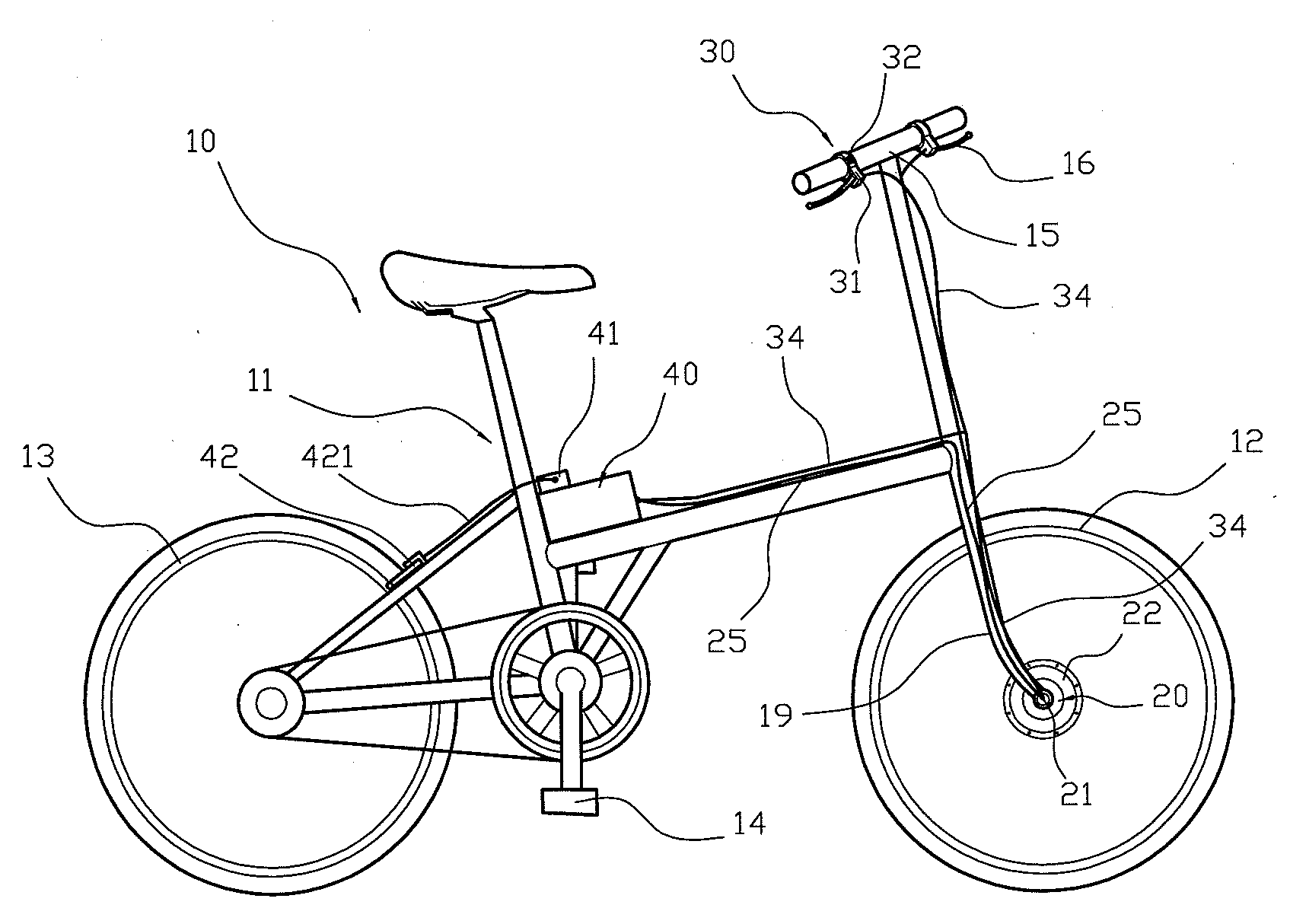
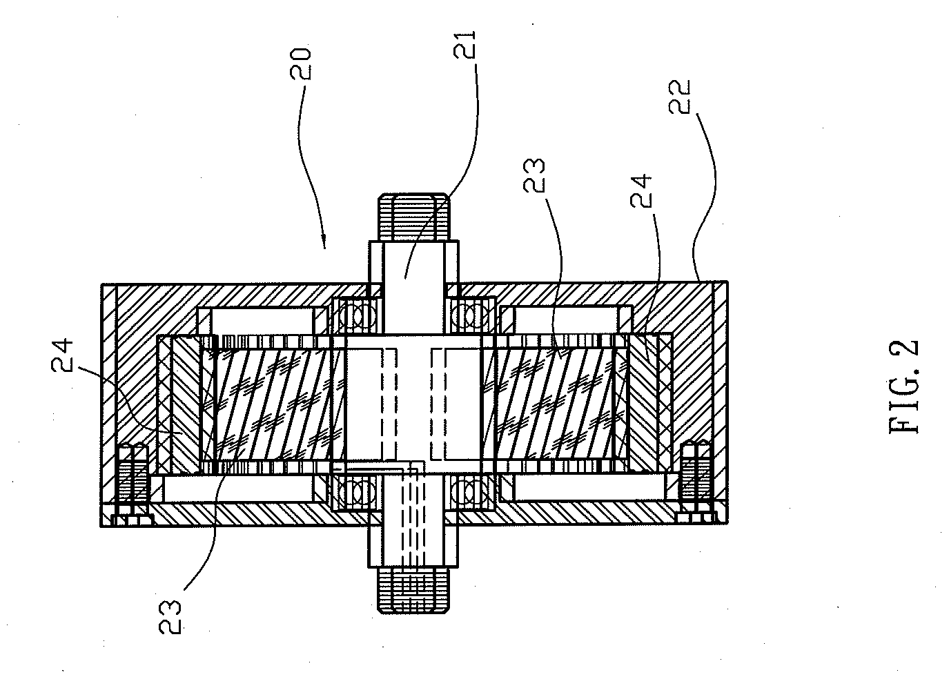
[0017]Referring to the drawings and initially to FIGS. 1-3, a motorized bicycle in accordance with the preferred embodiment of the present invention comprises a bicycle body 10, a rotation device 20 mounted on the bicycle body 10 and including a mandrel 21, a plurality of coils 23 mounted on the mandrel 21, a rotation member 22 rotatably mounted on the mandrel 21 and surrounding the coils 23, and a plurality of magnets 24 mounted in the rotation member 22 to move in concert with the rotation member 22 and movable to pass the coils 23, a chargeable battery 40 mounted on the bicycle body 10 and electrically connected to each of the coils 23 of the rotation device 20 to supply an electric power to each of the coils 23 of the rotation device 20, and a control device 30 mounted on the bicycle body 10 and including a microprocessor 31 electrically connected to the battery 40 and each of the coils 23 of the rotation device 20 to regulate the electric power from the battery 40 to each of th...


PUM


Abstract

A motorized bicycle includes a bicycle body, a rotation device, a chargeable battery and a control device. The rotation device includes a mandrel, a plurality of coils, a rotation member and a plurality of magnets. The control device includes a microprocessor and an adjusting switch. When the rotation device is disposed at the active state, the rotation device is driven by the electric power of the battery to move the bicycle forward, and when the rotation device is disposed at the passive state, the pedals are pedalled by the rider to rotate the front wheel, and the rotation device is driven by the front wheel to provide a generating function. The microprocessor can switch the active state and the passive state of the rotation device automatically to operate the electric power of the battery to the optimum extent.

Description

BACKGROUND OF THE INVENTION[0001]1. Field of the Invention[0002]The present invention relates to a bicycle and, more particularly, to a motorized bicycle.[0003]2. Description of the Related Art[0004]A conventional motorized bicycle in accordance with the prior art shown in FIG. 5 comprises a frame 51, a front wheel 50 a motor 60 and a storage battery 70. The motor 60 has an output gear 61 meshing with a serrated wheel rim 55 of the front wheel 50. The storage battery 70 is electrically connected to the motor 60. In operation, the storage battery 70 supplies an electric power to the motor 60 which drives the output gear 61 which drives the wheel rim 55 which drives the front wheel 50 so as to move the bicycle forward. Thus, the bicycle is moved forward by the electric power of the storage battery 70 so as to save a rider's energy. However, the electric power supplied by the storage battery 70 is not large enough so that the electricity of the storage battery 70 is easily consumed and...

Claims


Application Information

Patent Timeline
IPC IPC(8): B62M23/02B62M1/10
CPCB62M6/65
Inventor LIN, WEI-TING
Owner LIN WEI TING
Learn More