
Transmission device and method, reception device and method, and transmission/reception system

a technology of transmission device and reception device, applied in the field of transmission device and method, a reception device and method, and a transmission/reception system, can solve the problems of poor operability, difficult drag and drop operation for users unfamiliar with the operation of a computer, etc., to achieve simple and intuitive operation

Inactive Publication Date: 2010-11-04
SONY CORP
View PDF13 Cites 43 Cited by
  • Summary
  • Abstract
  • Description
  • Claims
  • Application Information

AI Technical Summary

Benefits of technology

[0008]However, the method of JP-A-2008-257442 constantly uses the outer edge portion of the screen for a connection to the outside. Thus, when it is applied to a portable terminal or the like having a small screen, operability worsens since the display region is narrow.
[0011]It is desirable to exchange data by a more simple and intuitive operation.
[0024]According to the first to third embodiments of the present invention, it is possible to exchange data by a more simple and intuitive operation.

Problems solved by technology

Thus, when it is applied to a portable terminal or the like having a small screen, operability worsens since the display region is narrow.
However, since the drag and drop operation is different from an operation in which a user transfers an object to another user in the real world, the drag and drop operation is not easy for users unfamiliar with the operation of a computer.
When the method is applied to a portable terminal having a small screen, operability worsens since the display region is narrow.
Since the drag and drop operation is different from an operation in which a user transfers an object to another user in the real world, the drag and drop operation is not easy for users unfamiliar with the operation of a computer.

Method used


Image

  • Transmission device and method, reception device and method, and transmission/reception system
  • Transmission device and method, reception device and method, and transmission/reception system
  • Transmission device and method, reception device and method, and transmission/reception system

Examples


Embodiment Construction

[0034]Hereinafter, embodiments of the present invention will be described with reference to the drawings.

[Configuration Example of Transmission / Reception System]

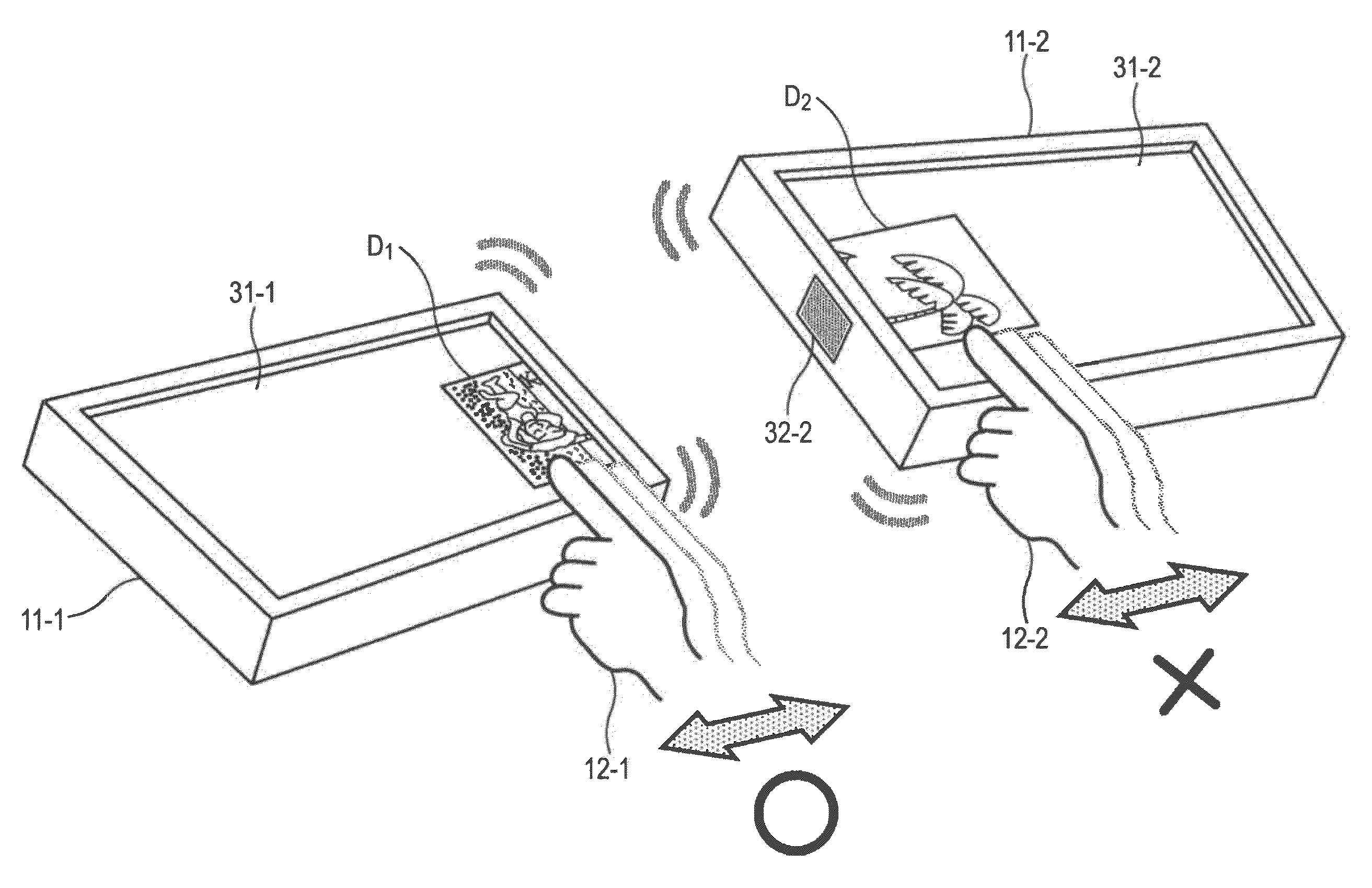
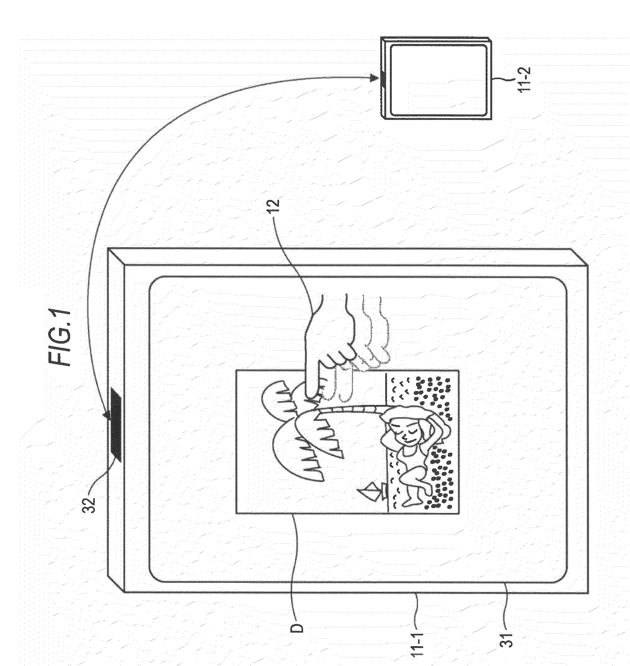
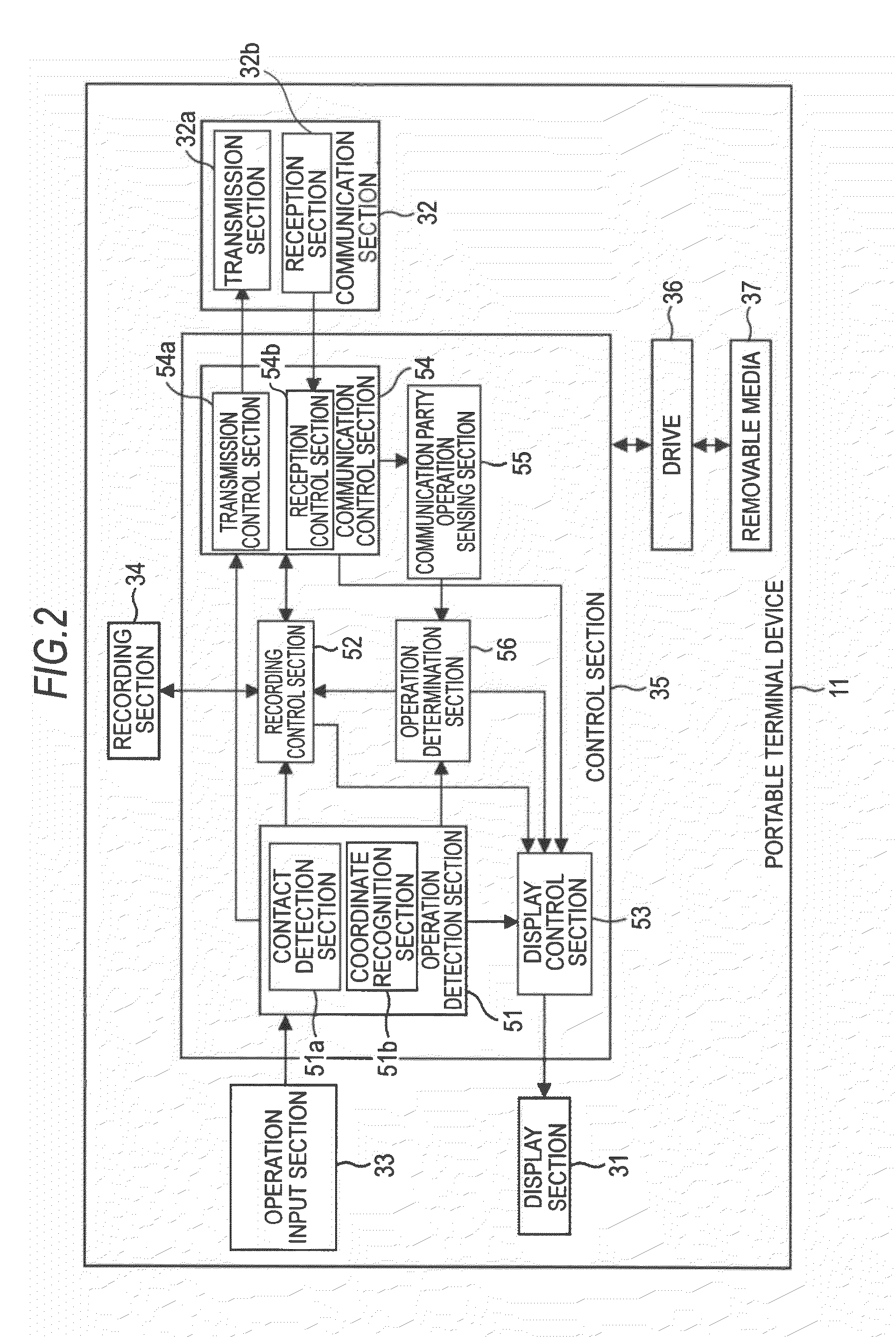
[0035]FIG. 1 is a block diagram showing a configuration example of a transmission / reception system according to an embodiment of the present invention. The transmission / reception system of FIG. 1 includes portable terminal devices 11-1 and 11-2. For example, the portable terminal devices 11-1 and 11-2 are constituted as a portable phone or a PDA (Personal Digital Assistant), and transmit / receive data therebetween by establishing a wired or wireless connection to each other so that communication is possible. Hereinafter, in the case where it is not necessary to distinguish the portable terminal devices 11-1 and 11-2, they are simply referred to as the portable terminal devices 11.

[0036]As shown in FIG. 1, the portable terminal device 11 (11-1) is operated by a user 12 and is provided with a display section 31 and a communicat...


PUM


Abstract

A transmission device for transmitting data to a reception device as a data destination, includes: a display control means for controlling display of an icon corresponding to the data directed to a first display section as a touch panel; an operation detection means for detecting an operation of a first user on the first display section on which the icon is displayed; a destination operation sensing means for sensing an operation of a second user on a second display section as a touch panel on which part of the icon is displayed in the reception device when the icon is held in a predetermined region of the first display section; and a transmission control means for controlling the start of transmission of the data to the reception device when the operation detection means detects that the icon is opened in the predetermined region of the first display section from a state in which the icon is held in the predetermined region of the first display section and the part of the icon is held in the second display section.

Description

BACKGROUND OF THE INVENTION[0001]1. Field of the Invention[0002]The present invention relates to a transmission device and method, a reception device and method, and a transmission / reception system, and more particularly to a transmission device and method, a reception device and method, and a transmission / reception system that can exchange data by a more simple and intuitive operation.[0003]2. Description of the Related Art[0004]In the past, various technologies for a data transmission method have been proposed.[0005]For example, there is a technique in which a user transmits data to a portable terminal possessed by the user by dragging and dropping a data icon to a transmission region arranged in an outer edge portion on a screen of an electronic notice device (see JP-A-2008-257442).[0006]A display device has been proposed in which data is transmitted by recognizing a memory card or a portable terminal connected to a personal computer via a connection interface as a storage device...

Claims


Application Information

Patent Timeline
IPC IPC(8): G06F3/01G06F3/048G06F3/0488
CPCG06F3/0488
Inventor INABA, TAKUYA
Owner SONY CORP
Learn More