
Touch panel input assisting device, computer operating method using the device, and tactile sense interlocking program

a technology of touch panel input and input assisting, which is applied in the direction of instruments, computing, electric digital data processing, etc., can solve the problems of inability to make the operation using a finger or a stylus on the touch panel feel the tactile feedback, and the structure becomes complicated

Inactive Publication Date: 2010-11-04
TOKYO INST OF TECH
View PDF4 Cites 34 Cited by
  • Summary
  • Abstract
  • Description
  • Claims
  • Application Information

AI Technical Summary

Benefits of technology

[0008]This invention uses a rolling unit as a means to apply a feeling of not only unevenness but reaction force to a finger. And by making a program synchronize with such a tactile feedback, operation of the program can be confirmed through the tactile sense, and the usability of a user interface and the presence of a game are improved. Moreover, in this invention, a touch panel input assisting device is applied to the touch panel, which functions alone (independently) and can be operated also by the finger or a stylus, by equipping the touch panel with the apparatus separately, by equipping the finger with the apparatus or by holding the apparatus with the finger. Therefore, the means to equip the touch panel with the apparatus so that the attachment and detachment are possible, or the holding or the wearing means for the finger to be equipped with the apparatus is established in this invention. Thus, it became possible to exclude the sensing function by the side of the touch-panel-input-assisting-device, and to reduce the device cost sharply by detecting movement of a finger utilizing the sensing function (i.e. contact position detection mechanism) of the existing touch panel. Moreover, the structure for equipping a finger with the touch-panel-input-assisting-device is established in one of embodiments of this invention. Such a concept of having equipped a finger with the touch-panel-input-assisting-device and operating a touch panel with it is new and does not exist previously. Although there may be some structure which can be interpreted also as a type of rolling unit, rolling on the position detecting sensor in the conventional joy stick, as it contains sensing function equipment in itself, its structure becomes complicated and the cost also becomes high, unlike this invention.
[0009]This invention was made in view of the above situation and uses a special instrument interposed between a finger and a touch panel in which the tactile feedback lacks for its operation, and thereby it gives a tactile feeling of the reaction force or the uneven surface to the finger under the operation and, by controlling a program to synchronize with these tactile feeling, it improves the usability of a user interface and the presence of a game and offers the touch-panel-input-assisting-device, which can be produced at a low cost by utilizing the sensing function of a touch panel, a computer operating method using the device, and a program synchronized with the tactile feeling. A means for giving reaction force to a finger is hereafter called a “reaction-force-generation-means”.

Problems solved by technology

Although there may be some structure which can be interpreted also as a type of rolling unit, rolling on the position detecting sensor in the conventional joy stick, as it contains sensing function equipment in itself, its structure becomes complicated and the cost also becomes high, unlike this invention.
In addition, the conventional input operation using a finger or a stylus on the touch panel were not able to make the operator feel the tactile feedback such as a resistance force, reaction force, a feeling of unevenness, or vibration.

Method used


Image

  • Touch panel input assisting device, computer operating method using the device, and tactile sense interlocking program
  • Touch panel input assisting device, computer operating method using the device, and tactile sense interlocking program
  • Touch panel input assisting device, computer operating method using the device, and tactile sense interlocking program

Examples


Embodiment Construction

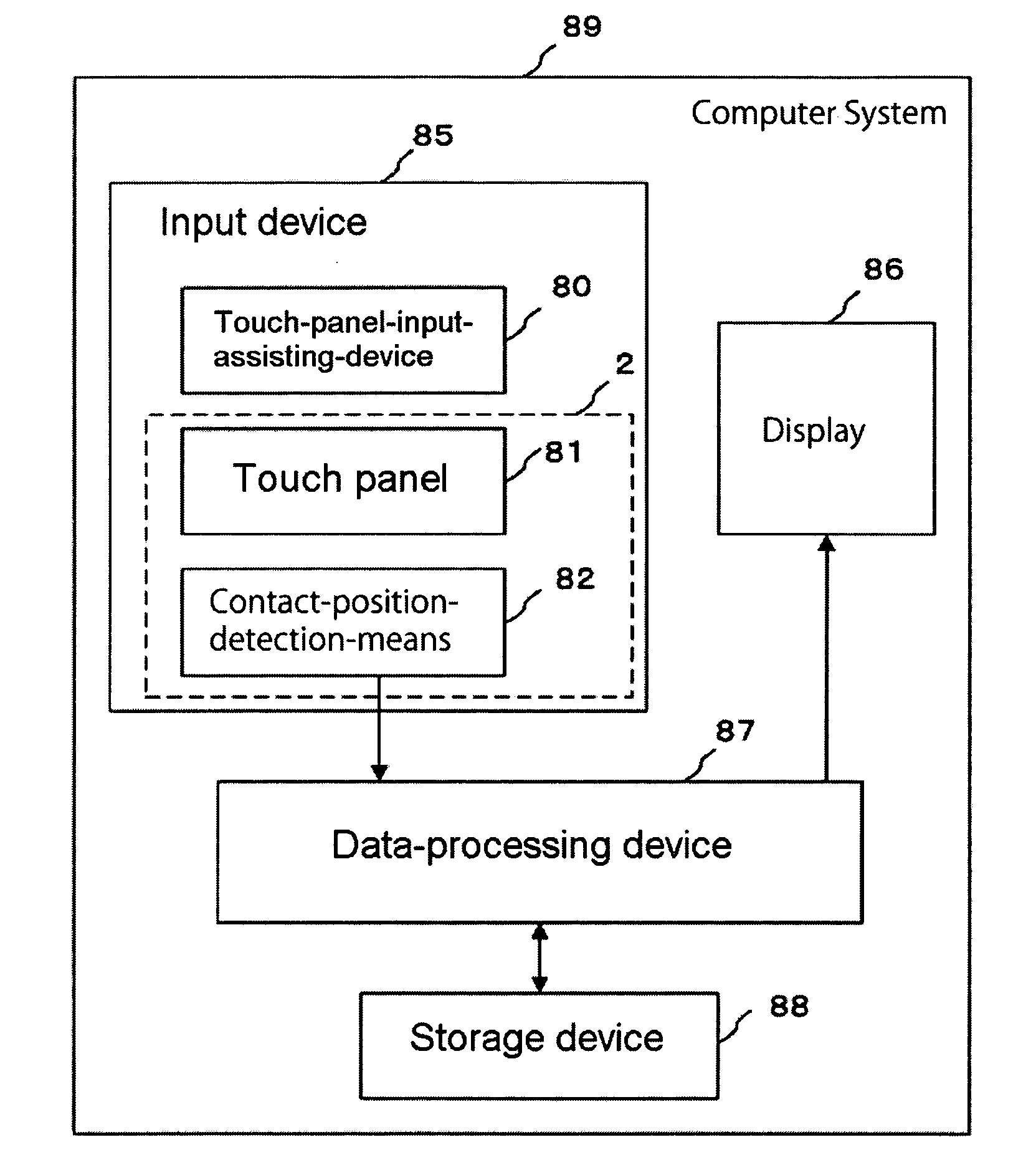
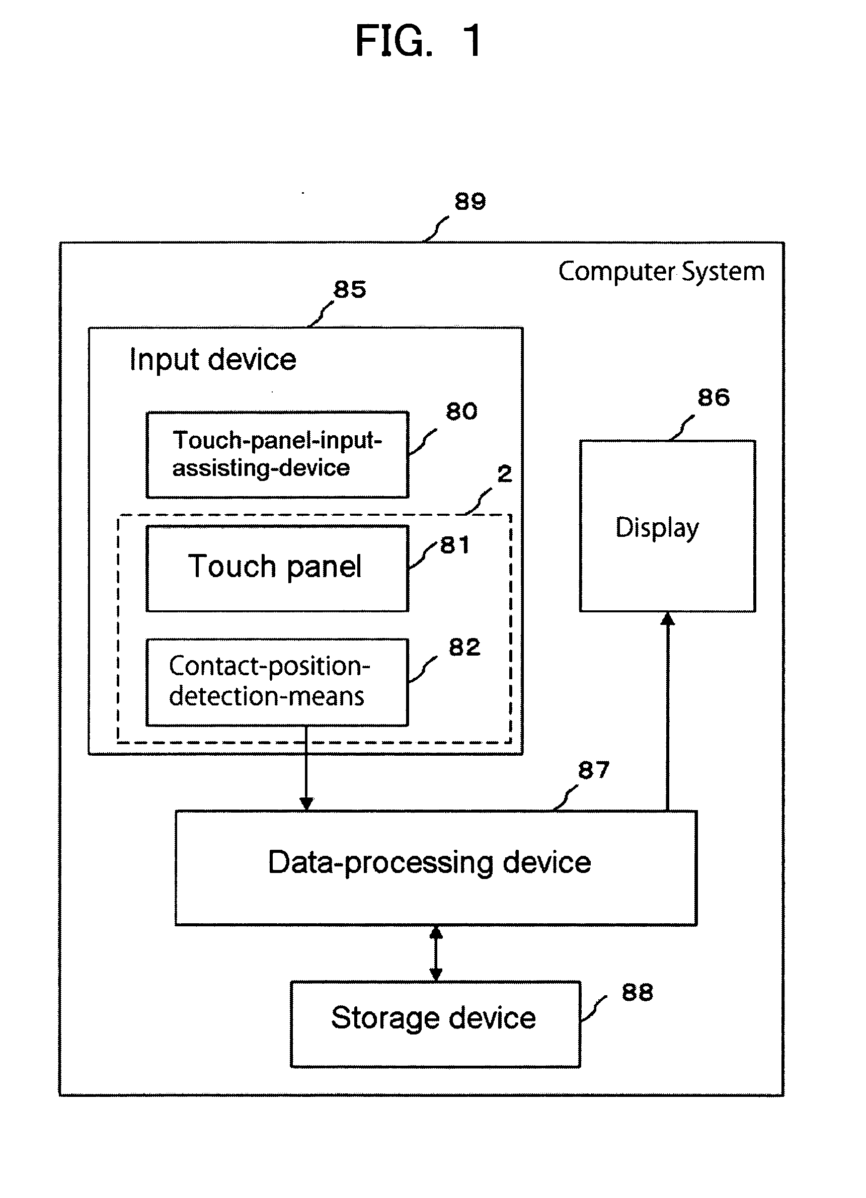
[0013]FIG. 1 is a functional block diagram of a computer system 89 which uses a touch-panel-input-assisting-device 80 as a data input device. The computer system 89 includes an input device 85 which inputs data, a data-processing device 87 which performs the data processing of a program using the inputted data, an output device 86 which outputs the result of the processing, and a storage device 88 which stores data. Moreover, the input device 85 includes a touch panel 2 which consists of a panel 81 and a contact-position-detection-means 82, and the touch-panel-input-assisting-device 80 which inputs data to the device 80 through this touch panel 2. The computer system 89 can be a general-purpose personal computer or may be a game machine or a music player for exclusive use. The touch-panel-input-assisting-device 80 of this invention is used in combination with the panel 81 equipped with the contact-position-detection-means 82 prepared separately from it as shown in FIG. 1. Hereafter,...


PUM


Abstract

[PROBLEMS] To detect any of various movements of a finger by using the touch panel of an existing device and to give tactile sense to facilitate operation.[MEANS FOR SOLVING PROBLEMS] A touch panel input assisting device attached to an existing device having a touch panel or held by fingers so as to use it. Any of various movements of a finger is transformed into rolling of a rolling unit on a touch panel or deformation thereof, the rolling or deformation is detected as a variation of the position or area of the contact of the rolling unit with the touch panel, and a tactile sense such as a reactive force, a resistance force, vibration, or a sensation of roughness is given to the finger. A tactile interlocking program for analyzing the movement pattern and speed pattern of the point of contact of the rolling unit with the touch panel and estimating the movement of the finger is used to perform a predetermined operation interlockingly with the movement of the finger or tactile sense given to the finger.

Description

TECHNICAL FIELD [0001]The present invention relates to a touch panel input assisting device that converts various finger movements into contact patterns by a rolling motion of a rolling unit on a touch panel while giving reaction force, such as a resistance force or repulsive force to the finger; and a computer operating method to detect the timing of the original finger movements or the reaction force being exerted to the finger based on the change patterns of the position or speed of a contact point of the rolling unit on the touch panel and to execute a computer by synchronizing the timing with the computer and a tactile sense interlocking program.BACKGROUND ART[0002]Conventionally, a finger or a pen-like-instrument called a stylus has been used to contact the touch-panel surface, and to input coordinates of the contact point. However, in either case, tactile feedback has been insufficient and, as a result, visual or auditory sense has been needed to confirm whether the input was...

Claims


Application Information

Patent Timeline
IPC IPC(8): G06F3/041G06F3/0338G06F3/0354
CPCG06F3/0338G06F2203/0331G06F3/038G06F3/03545
Inventor KUMAZAWA, ITSUO
Owner TOKYO INST OF TECH
Learn More