Continuous circuit overlay solar shingles

a solar shingle and continuous circuit technology, applied in the direction of pv power plants, connection contact material, coupling device connections, etc., can solve the problems of not giving consumers enough financial incentives, the initial cost of installing such a system is still commercially illusive, and the industry has yet to develop photovoltaic devices with enough efficiency

Active Publication Date: 2010-11-04
RUSKIN RAYMOND H
View PDF3 Cites 31 Cited by
  • Summary
  • Abstract
  • Description
  • Claims
  • Application Information

AI Technical Summary

Problems solved by technology

The idea of fitting new houses and re-fitting old houses with photovoltaic roofing or roof-mounted systems has been widely embraced as an environmentally beneficial goal, but one that still remains commercially illusive in the mass roofing market.
First, the initial cost of installing such a system has not given consumers enough financial incentive in future returns to choose to install a home roof-mounted solar system.
But, to date, the industry has yet to develop photovoltaic devices with enough efficiency to offset the other cost factors involved in a solar roofing system, namely production, customization, and the specialized skills required for installation.
Second, the most common retro-fitted solar roof systems are superimposed independent structures that attach over existing roofs which may compromise the integrity of the existing roofing material, void the roof warranty, and make roof maintenance or replacement costly and complicated.
Third, current available solar roof systems lack the ability to conform to most roof shapes and irregularities without the creation of customized components.
Fourth, retro-fitted superimposed solar systems are generally not aesthetically pleasing.
A solar roof shingle system such as taught by U.S. Pat. No. 5,575,861 addresses aesthetics and integration, but requires access to the roof decking underside and tedious wiring labor.
Specialized labor not only drives up the cost of installation, but limits consumer options for future serviceability.

Method used


Image

  • Continuous circuit overlay solar shingles
  • Continuous circuit overlay solar shingles
  • Continuous circuit overlay solar shingles

Examples


Embodiment Construction

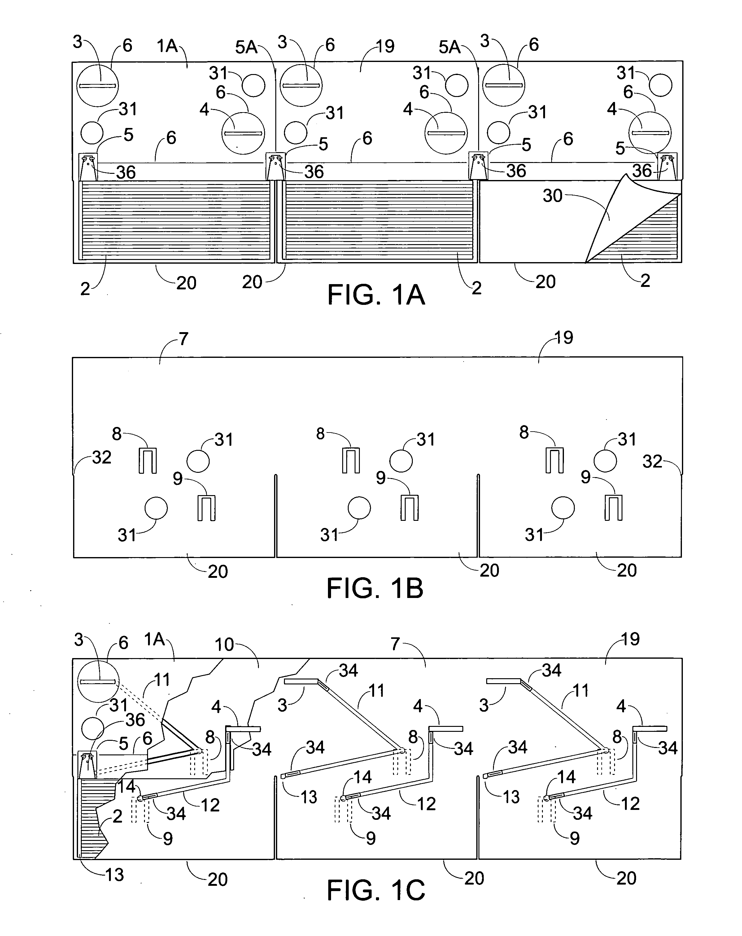
[0049]The present invention relates to a solar shingle roofing system, including various components that comprise this roofing system, various relationships between components, and various configurations of electrical connectivity that characterize the roofing system. The function of this solar roofing system, as included in the scope of this invention, is two-fold: to provide a watertight protective roofing surface and to transform solar energy from a plurality of photovoltaic devices to a consolidated and predetermined conduit of electrical current. It is to be understood that this invention can employ any photovoltaic device, regardless of form or efficiency, regardless of whether it is a cell, film, coating, or any other form and that all such photovoltaic devices can be incorporated into this roofing system. It is also to be understood that the shingles can be fabricated from any one or combination of a variety of pliable, waterproof, non-conductive, tear-resistant materials co...


PUM


Abstract

A solar roofing system includes components that can be made to mimic traditional tabbed asphalt roofing shingles in size, shape, and performance. Additionally, the shingles also include photovoltaic devices embedded in the shingle tabs. Shingles are installed in a traditional manner using traditional tools and fasteners in offset and overlapping rows. Electrical connectivity among tabs is made by contact between top and bottom surfaces of shingles without the need for additional wiring or hardware. The system includes multiple shingle shapes including a variation that can be cut apart into separate tabs. This solar roofing system can be integrated with non-photovoltaic components to fit irregularities found in a variety of roof surfaces. The system, once installed, creates a redundancy of electrical connectivity throughout a roof surface to allow for interruptions and irregularities in the roof surface and to allow for highly reliable output performance.

Description

CROSS REFERENCE TO OTHER RELATED APPLICATIONS[0001]This application is a Continuation in Part of patent application Ser. No. 12 / 387,527, filled on May 4, 2009.FEDERALLY SPONSORED RESEARCH OR DEVELOPMENT[0002]None.BACKGROUND OF THE INVENTION[0003]The idea of fitting new houses and re-fitting old houses with photovoltaic roofing or roof-mounted systems has been widely embraced as an environmentally beneficial goal, but one that still remains commercially illusive in the mass roofing market. There are several reasons for this.[0004]First, the initial cost of installing such a system has not given consumers enough financial incentive in future returns to choose to install a home roof-mounted solar system. Therefore the technological focus has been primarily on greater photovoltaic efficiency. But, to date, the industry has yet to develop photovoltaic devices with enough efficiency to offset the other cost factors involved in a solar roofing system, namely production, customization, and ...

Claims


Application Information

Patent Timeline
Patent Type & Authority Applications(United States)
IPC IPC(8): E04D13/18E04D1/34H01R13/02
CPCE04D1/26E04D1/34E04D2001/3429H02S20/25Y02B10/12H02S40/36H02S20/23H01R4/58Y02E10/50Y02B10/10E04D1/2916E04D1/30E04D1/2918
Inventor RUSKIN, RAYMOND HENRYKINSLEY, HOMAN B.
Owner RUSKIN RAYMOND H
Why Eureka
Try Eureka