
Control system for controlling an industrial robot

a control system and industrial robot technology, applied in the field of control systems, can solve the problems of difficult to add a new function or replace some parts of the control system, the available hardware is rarely used in an optimal manner, and it is difficult to achieve the effect of increasing the capacity of the hardware unit, high priority, and high performance of selected system functions

Inactive Publication Date: 2010-10-28
ABB TECH AG
View PDF11 Cites 14 Cited by
  • Summary
  • Abstract
  • Description
  • Claims
  • Application Information

AI Technical Summary

Benefits of technology

[0009]Each software module is adapted to perform a function of the control system. With a system function is meant any function carried out by the control system, such as servo control, path planning, safety functions, communication, I / O-handling, user interface, process control, and language handling. A scalable software module is adapted to perform its system function with different degrees of performance, for example with different degrees of accuracy, quality and / or quantity, in dependence on the capacity, for example computing power and memory storage, of the hardware unit hosting and running the software module. Thus, the performance of the system function performed by the module is dependent on the capacity of the hardware unit hosting it. An advantage with scalable software modules is that they can utilize the available hardware in an optimal manner. Further, if it is a desire, the performance of a certain system function can easy be increased by moving the software module to another hardware unit with more available capacity, or if there is more than two software modules on the same hardware unit, by moving the other software module to another hardware unit with available capacity. Such a control system is very flexible. It is easy to add new hardware units in order to increase the hardware capacity of the control system, and thereby to increase the performance of the system functions.
[0010]The resource-distributing unit has knowledge of the capacity of the hardware units and the demand on hardware capacity of the software modules, and is configured to plan how to distribute the software modules among the hardware units in order to optimize the performance of the system functions. In order to be able to optimize the performance of the control system, the resource-distributing unit must also have knowledge of the scalability of the software modules, i.e. how much performance the module can provide in dependence on how much hardware capacity it gets, for example, the number of performance levels provided by the software module and the hardware capacity required by each level. The recourse-distributing unit considers the scalability of the software modules and distributes the software modules such that the performances of the system functions are optimized. Thus, the hardware of the control system is utilized in an optimal manner. The invention makes it possible to optimize the performance of control system regarding the quality as well as quantity by distributing the software modules on the hardware units in an optimized way. Thereby a completely flexible control system is achieved.
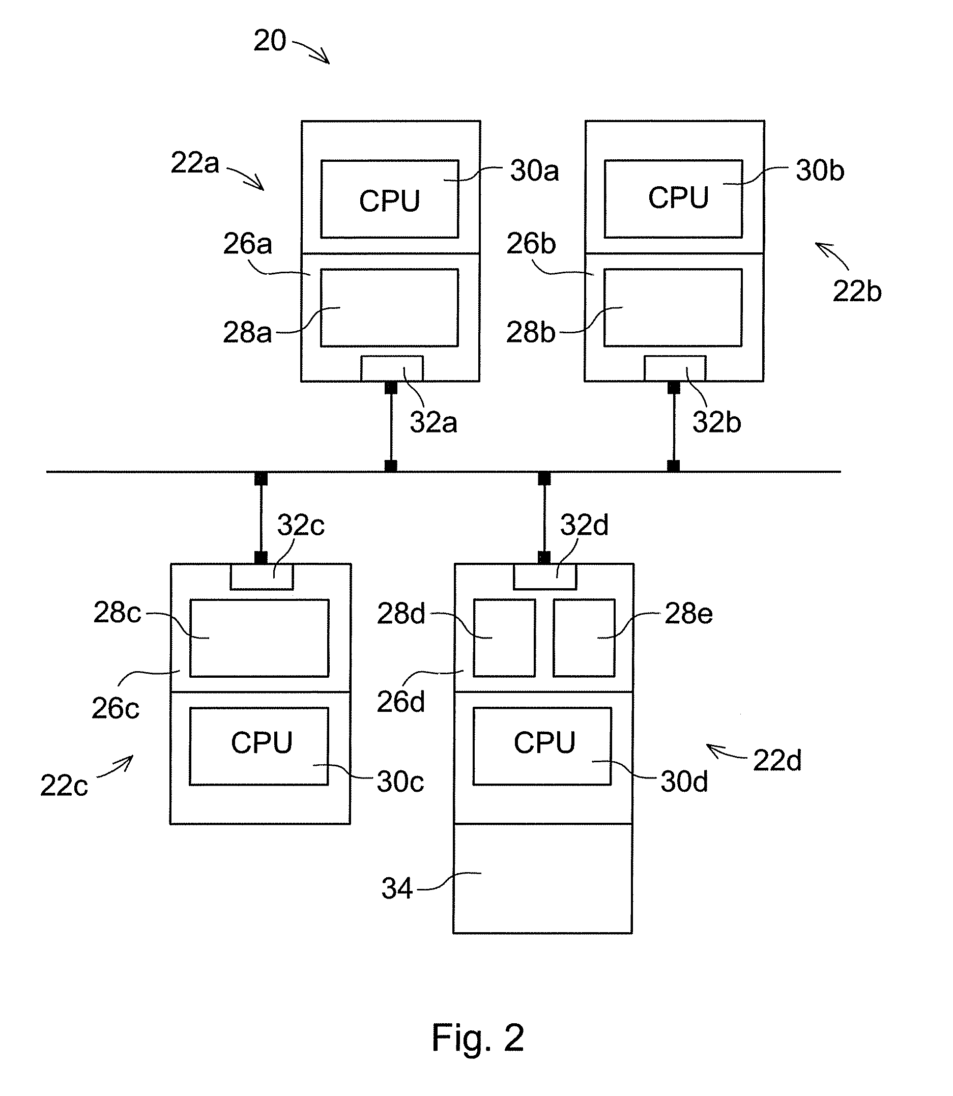
[0011]According to an embodiment of the invention, the control system comprises an internal network. Each of said hardware units is arranged as a node in the internal network, and each hardware unit comprises a communication unit for communicating with all the other nodes in the internal network. By connecting the hardware units to an internal network, instead of a bus as in the prior art, it is possible for each hardware unit to communicate directly with all the other modules, regardless of where the modules are placed physically relative to each other. Further because the functions of the control system has been divided into a plurality of software modules loaded onto separate hardware units connected to and adapted to communicate with each other over a internal network it is made possible to add or remove capacity and / or a function of the control system by connecting or disconnecting a hardware unit to or from the internal network. Thereby it is possible to adapt the performance and functionality of the control system depending on the current application.
[0014]According to an embodiment of the invention, the scalable software modules have been assigned different priorities and the resource-distributing unit is configured to plan how to distribute the software modules based on their priorities. This embodiment makes it possible to set different priorities to different system functions, and thereby enabling high performance of selected system functions, which are given a high priority. For example, if a smooth path is desired the path planner function is assigned a high priority.
[0015]According to an embodiment of the invention, the software modules are scalable in two or more consecutive scaling steps, each scaling step having a defined demand on hardware capacity, and each subsequent step having an increased demand on the capacity of the hardware unit, and the software modules provides an increased performance of their system function for each subsequent step. This embodiment makes it easy for the resource-distributing unit to match the software modules with the hardware units in an optimal manner.

Problems solved by technology

One disadvantage of control system today is that they are inflexible.
Another disadvantage with the control systems of today is that available hardware is seldom used in an optimal manner.
However, this is a traditional multi-CPU solution with a fixed number of CPU:s. A disadvantage with this system is that it is inflexible, and it is difficult to add a new function or replace some part of the control system.

Method used


Image

  • Control system for controlling an industrial robot
  • Control system for controlling an industrial robot
  • Control system for controlling an industrial robot

Examples


Embodiment Construction

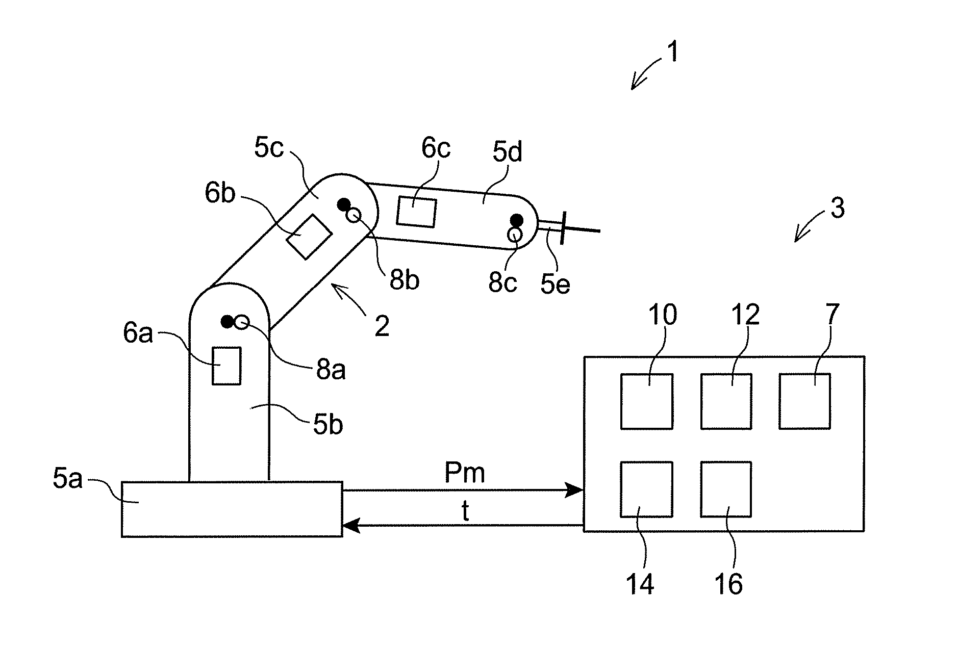
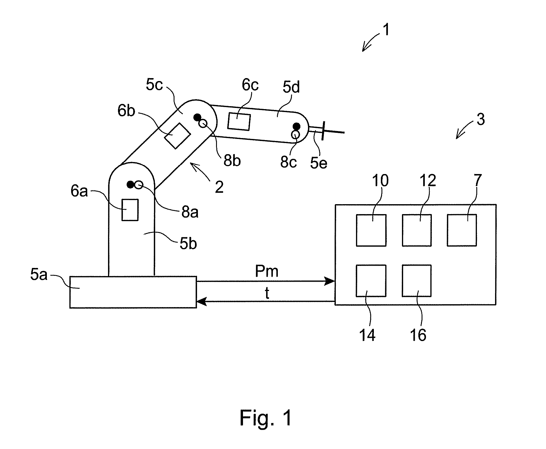
[0024]FIG. 1 shows a conventional industrial robot 1 comprising a manipulator 2 and a control system 3. The industrial robot 1 has a plurality of robot parts rotatably movable relative to each other. The robot parts are in this case a stand 5a, robot arms 5b-d, and a tool holder 5e. The industrial robot comprises a plurality of actuators 6a-c for controlling the position and speed of the robot parts. The actuators are connected to a servo control unit 7 for generating control signals to the motor and located in the control system 3. The manipulator is also provided with sensors 8a-c detecting the position of the robot parts. Signals comprising measured data Pm from the sensors 8a-c are transmitted to the control system 3. The measured data comprises, for instance, angular position, velocity, and acceleration.

[0025]The control system 3 comprises a main computer unit 10, a memory unit 12 for storing control programs including movement instructions for the robot, a program executor uni...


PUM


Abstract

A control system for controlling at least one industrial robot, wherein the control system comprises a plurality of software modules (41-47) for handling various system functions of the control system, and a plurality of separate hardware units (50-53), each comprising a processing unit (30a-d) and a memory unit (26a-d) for storing one or more of said software modules, and each of the hardware units is configured to receive and execute one or more of the software modules. At least some of the software modules are arranged scalable with regard to the performance of the system functions dependent on the capacity of the hardware unit running the software module, and the control system comprises a resource-distributing unit (55) having knowledge of the capacity of the hardware units, the scalability of the software modules, and the demand on hardware capacity of the software modules, and the resource-distributing unit is configured to plan how to distribute said software modules among said hardware units in order to optimized the performance of the system functions.

Description

TECHNICAL FIELD[0001]The present invention relates to a control system for controlling at least one industrial robot, wherein the control system comprises a plurality of software modules for handling various system functions of the control system, and a plurality of separate hardware units, each comprising a processing unit and a memory unit for storing one or more of said software modules, and each of the hardware units is configured to receive and execute one or more of the software modules.BACKGROUND ART[0002]An industrial robot comprises a manipulator and a control system for controlling the movements of the manipulator. A manipulator is a movable mechanical unit, the movements of which are driven by one or more motors. Traditionally, the control system of an industrial robot comprises a stationary control device including a main control unit, a servo control unit providing the motors with current, and a handheld control device. The stationary control device comprises hardware, ...

Claims


Application Information

Patent Timeline
IPC IPC(8): B25J9/16G06F9/50G05B19/414
CPCG05B19/4141G05B2219/33334G06F9/5066G05B2219/39252G05B2219/36395
Inventor ERIKSSON, PETER J.
Owner ABB TECH AG
Learn More