
Soft Clock Delay for OCT System and Method Therefor

Active Publication Date: 2010-10-28
EXCELITAS TECH
View PDF6 Cites 62 Cited by
  • Summary
  • Abstract
  • Description
  • Claims
  • Application Information

AI Technical Summary

Benefits of technology

[0010]The present invention concerns an alternate approach that is implemented in software. The electronic delay is eliminated at the cost of increased processing time and an additional calibration step during manufacturing. On the other hand, the overall system cost and size are reduced while yielding a system that is more flexible in its ability to compensate for different OCT probes, for example.

Problems solved by technology

While having advantages over optical delay solutions, the electronic clock delays can be costly in terms of the required electronics.
Such delay systems can be expensive and have relatively high power consumption since the transistors are operated in the saturation region, constantly drawing current.

Method used


Image

  • Soft Clock Delay for OCT System and Method Therefor
  • Soft Clock Delay for OCT System and Method Therefor
  • Soft Clock Delay for OCT System and Method Therefor

Examples


Embodiment Construction

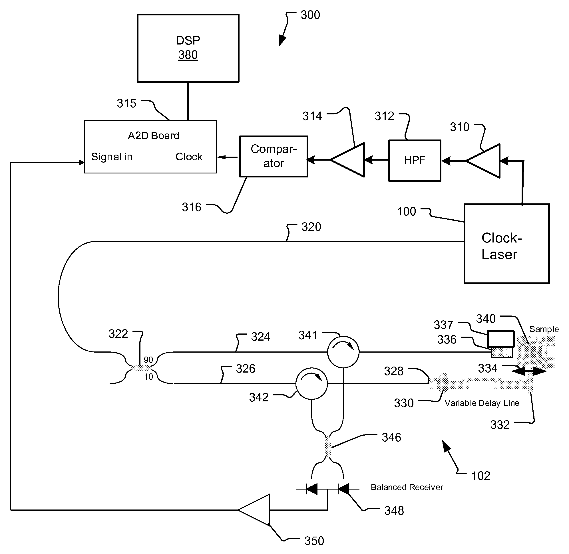
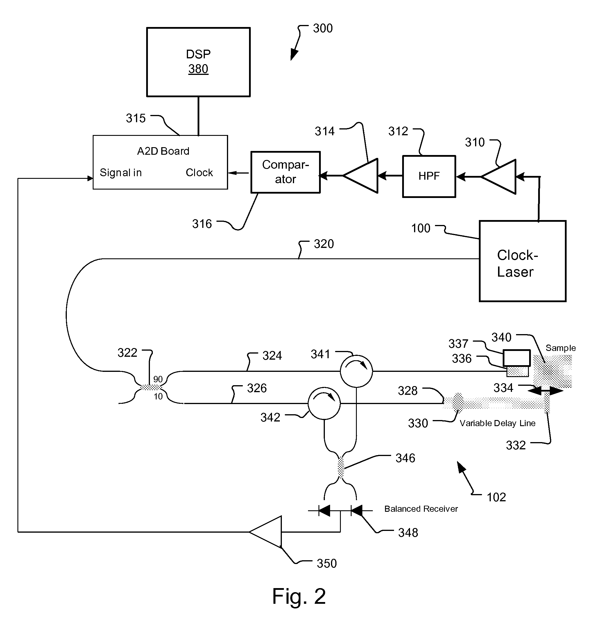
[0024]FIG. 2 shows an optical coherence analysis system 300 using an integrated k-clock-swept source laser module 100 but without the typical delay for the k-clock. In the preferred embodiment, the k-clock-swept / source laser module 100 is constructed as described in incorporated U.S. patent application Ser. No. 12 / 396,099.

[0025]In more detail, a Michelson interferometer 102 is used to analyze the optical signals from the sample 340. Light from the swept source laser module 100 is output on fiber 320 to a 90 / 10 optical coupler 322. The tunable signal is divided by the coupler 322 between a reference arm 326 and a sample arm 324 of the system.

[0026]The optical fiber of the reference arm 326 terminates at the fiber endface 328. The light exiting from the reference arm fiber endface 328 is collimated by a lens 330 and then reflected by a mirror 332 to return back.

[0027]The external mirror 332 has an adjustable fiber to mirror distance (see arrow 334). This distance determines the depth ...


PUM


Abstract

An optical coherence analysis system comprises a swept source laser for generating optical signals that are tuned over a scan band; an interferometer for transmitting the optical signals over a sample arm and reference arm and combining the optical signals; a k-clock for generating a sampling clock indicating non-linearities in the frequency tuning of the optical signals over the scan band, the k-clock being not delay matched to propagation delays for the optical signals in the interferometer; a sampling system for sampling the optical signals from the interferometer in response to the k-clock to generate interference signals; and a processing system for determining non-linearities in the sampling clock and for transforming the interference signals into an image of a sample in response to the non-linearities. The system compensates for the lack of an electronic delay of k-clock using a nonuniform discrete Fourier transform.

Description

BACKGROUND OF THE INVENTION[0001]Optical Coherence Tomography (OCT) is a form of optical coherence analysis that is typically used to perform high-resolution cross sectional imaging. It is often applied to imaging biological tissue structures, for example, on microscopic scales in real time. Optical waves are sent through an object or sample and a computer produces images of cross sections of the object by using information on how the waves are changed.[0002]A common type of optical coherence analysis is termed Fourier domain OCT (FD-OCT). These Fourier domain techniques often use a wavelength swept source and a single detector, sometimes referred to as time-encoded FD-OCT (TEFD-OCT) or swept source OCT (SS-OCT) since it has advantages in speed and signal-to-noise ratio (SNR). The spectral components are encoded in time. The spectrum is either filtered or generated in successive frequency steps and reconstructed before Fourier-transformation.[0003]In TEFD-OCT, critical performance c...

Claims


Application Information

Patent Timeline
IPC IPC(8): H04B10/08
CPCG01N21/4795H04B10/073G01B9/02069G01B9/02091G01B9/02004
Inventor JOHNSON, BARTLEY C.
Owner EXCELITAS TECH
Learn More