Detection setup for x-ray phase contrast imaging

a phase contrast and detection setup technology, applied in the field of x-ray devices, can solve the problems of not directly spatially resolved patterns, the pixel size of existing x-ray detectors is (much) larger than the distance between maxima, and the movement of optical elements is a nontrivial mechanical task, so as to achieve the effect of minimizing the exposure of objects

Active Publication Date: 2010-10-28
KONINKLIJKE PHILIPS ELECTRONICS NV
View PDF7 Cites 11 Cited by
  • Summary
  • Abstract
  • Description
  • Claims
  • Application Information

AI Technical Summary

Benefits of technology

[0018]The X-ray source may optionally comprise at least one filter, e.g. a filter which suppresses a certain band of the X-ray spectrum emitted by the X-ray source. Parts of the X-ray spectrum that are of no use for the desired phase contrast imaging or that even disturb such an imaging can thus be blended out. This helps to minimize the exposure of the object to X-radiation, which is particularly important in medical applications.

Problems solved by technology

A problem of the described approach is that the feasible pixel size of existing X-ray detectors is (much) larger than the distance between the maxima and minima of the interference pattern.
These patterns can therefore not directly be spatially resolved.
The necessary movement of optical elements is however a nontrivial mechanical task, particularly if it has to be done fast and with high accuracy, as would be required if phase contrast imaging shall be applied in a medical environment.

Method used


Image

  • Detection setup for x-ray phase contrast imaging
  • Detection setup for x-ray phase contrast imaging

Examples


Embodiment Construction

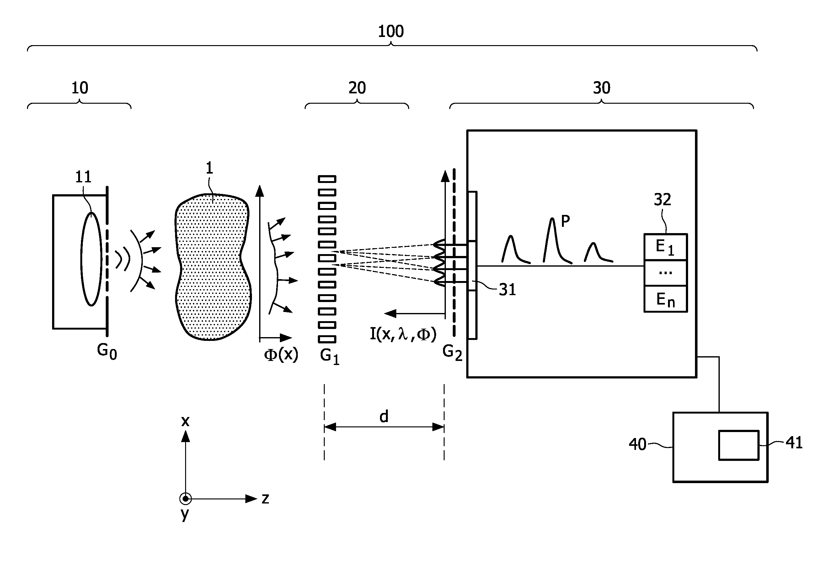
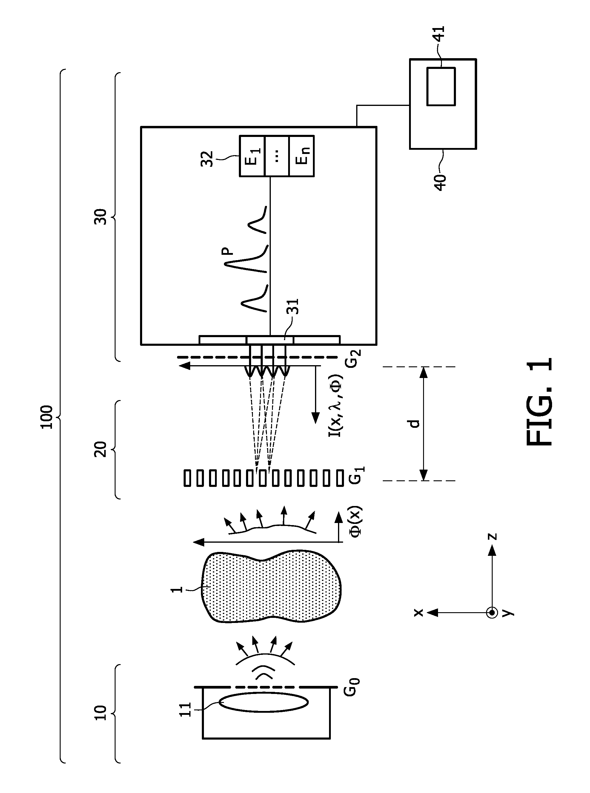
[0028]These and other aspects of the invention will be apparent from and elucidated with reference to the embodiment(s) described hereinafter. These embodiments will be described by way of example with the help of the accompanying single drawing which schematically illustrates an X-ray device according to the present invention for generating phase contrast images of an object.

[0029]Phase contrast X-ray imaging aims at the measurement of the phase shift of X-rays as they pass through an object. The benefit of phase sensitive measurements is that the phase contrast is potentially orders of magnitude higher than the absorption contrast (cf. A. Momose, “Phase sensitive imaging and phase tomography using X-ray interferometers”, Optics Express 11(19), 2003; T. Weitkamp et al., “X-ray phase imaging with a grating interferometer”, Optics Express 13(16), 2005). Initially a major shortcoming of phase sensitive methods was that X-ray sources with a very narrow bandwidth were required. This sho...


PUM

PropertyMeasurementUnit
photon energyaaaaaaaaaa
phase contrastaaaaaaaaaa
phase shiftaaaaaaaaaa

Abstract

The invention relates to a method and a device for generating phase contrast X-ray images of an object (1). The device comprises an X-ray source (10) that may for example be realized by a spatially extended emitter (11) behind a grating (G0). A diffractive optical element (DOE), for example a phase grating (G1), generates an interference pattern (I) from the X-radiation that has passed the object (1), and a spectrally resolving X-ray detector (30) is used to measure this interference pattern behind the DOE. Using the information obtained for different wavelengths/energies of X-radiation, the phase shift induced by the object can be reconstructed.

Description

FIELD OF THE INVENTION[0001]The invention relates to an X-ray device and a method for generating phase contrast X-ray images of an object.BACKGROUND OF THE INVENTION[0002]While classical X-ray imaging measures the absorption of X-rays caused by an object, phase contrast imaging aims at the detection of the phase shift X-rays experience as they pass through an object. According to a design that has been described in literature (T. Weitkamp et al., “X-ray phase imaging with a grating interferometer”, Optics Express 13(16), 2005), a phase grating is placed behind an object to generate an interference pattern of intensity maxima and minima when the object is irradiated with (coherent) X-rays. Any phase shift in the X-ray waves that is introduced by the object causes some characteristic displacement in the interference pattern. Measuring these displacements therefore allows to reconstruct the phase shift of the object one is interested in.[0003]A problem of the described approach is that...

Claims


Application Information

Patent Timeline
Patent Type & Authority Applications(United States)
IPC IPC(8): G01N23/02
CPCA61B6/00A61B6/032A61B6/4291A61B6/484A61B6/06
Inventor KOEHLER, THOMAS
Owner KONINKLIJKE PHILIPS ELECTRONICS NV
Why Eureka
Try Eureka