
Sequence hopping method, wireless communication terminal apparatus and wireless communication base station apparatus

Inactive Publication Date: 2010-10-28
PANASONIC CORP
View PDF1 Cites 33 Cited by
  • Summary
  • Abstract
  • Description
  • Claims
  • Application Information

AI Technical Summary

Benefits of technology

[0018]According to the present invention, it is possible to improve the effect of randomization by sequence hopping by reducing interference between sequences in both reference signals before and after sequence hopping.

Problems solved by technology

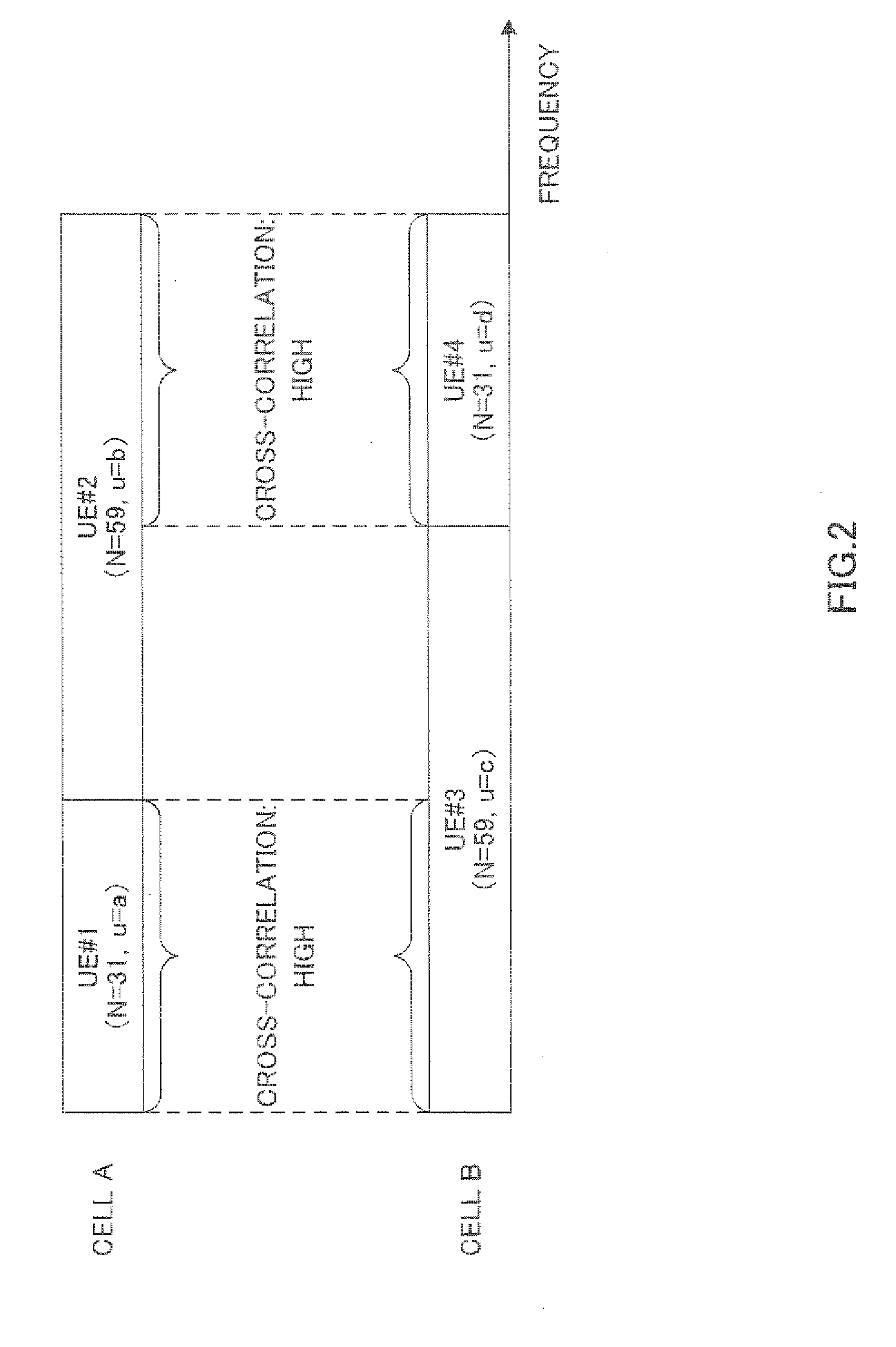
Consequently, in the frequency bands to which ZC sequences of high-cross correlation are allocated, that is, in the frequency bands to which the reference signal of UE #1 and the reference signal of UP #4 are allocated, interference of sequences of the reference signals between cell A and cell B increases, and therefore the accuracy of channel estimation deteriorates.

Method used


Image

  • Sequence hopping method, wireless communication terminal apparatus and wireless communication base station apparatus
  • Sequence hopping method, wireless communication terminal apparatus and wireless communication base station apparatus
  • Sequence hopping method, wireless communication terminal apparatus and wireless communication base station apparatus

Examples


embodiment 1

[0040]With the present embodiment, different amounts of hopping are given to a plurality of ZC sequences of varying sequence lengths.

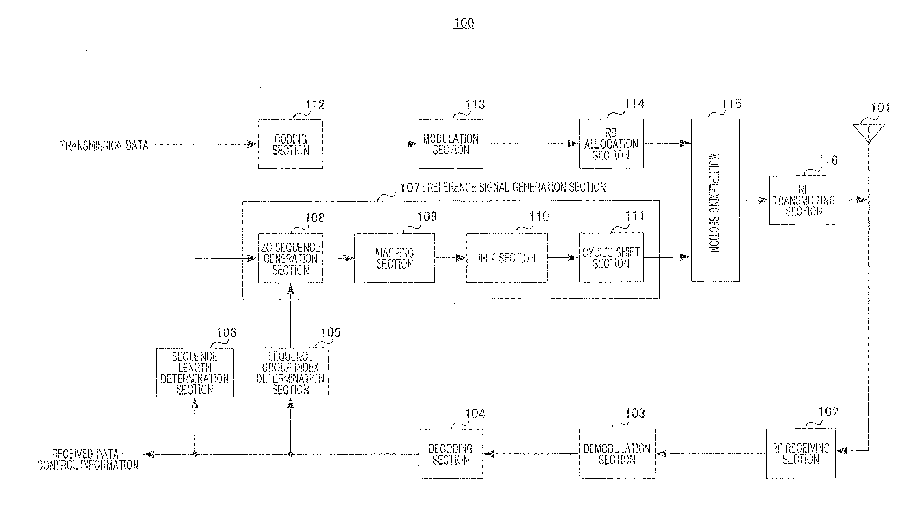
[0041]The configuration of terminal 100 according to the present embodiment will be described using FIG. 9.

[0042]RF receiving section 102 of terminal 100 shown in FIG. 9 performs receiving processing including down-conversion and A / D conversion on a signal received via antenna 101, and outputs the signal subjected to receiving processing to demodulation section 103.

[0043]Demodulation section 103 performs equalization processing and demodulation processing on the signal received as input from RF receiving section 102, and outputs the signal after these processing to decoding section 104.

[0044]Decoding section 104 decodes the signal received as input from demodulation section 103, and extracts received data and control information. Then, decoding section 104 outputs the sequence group index among the extracted control information to sequence index determ...

embodiment 2

[0100]With the present embodiment, in addition, different offsets between ZC sequences of varying sequence lengths are given to ZC sequences to use for reference signals in slot #1 (i.e. reference signals before hopping) in one subframe.

[0101]Now, an example of setting offsets and the amount of hopping of sequence indexes in sequence index determination section 105 of terminal 100 (FIG. 9) and sequence index determination section 164 of base station 150 (FIG. 10) will be explained.

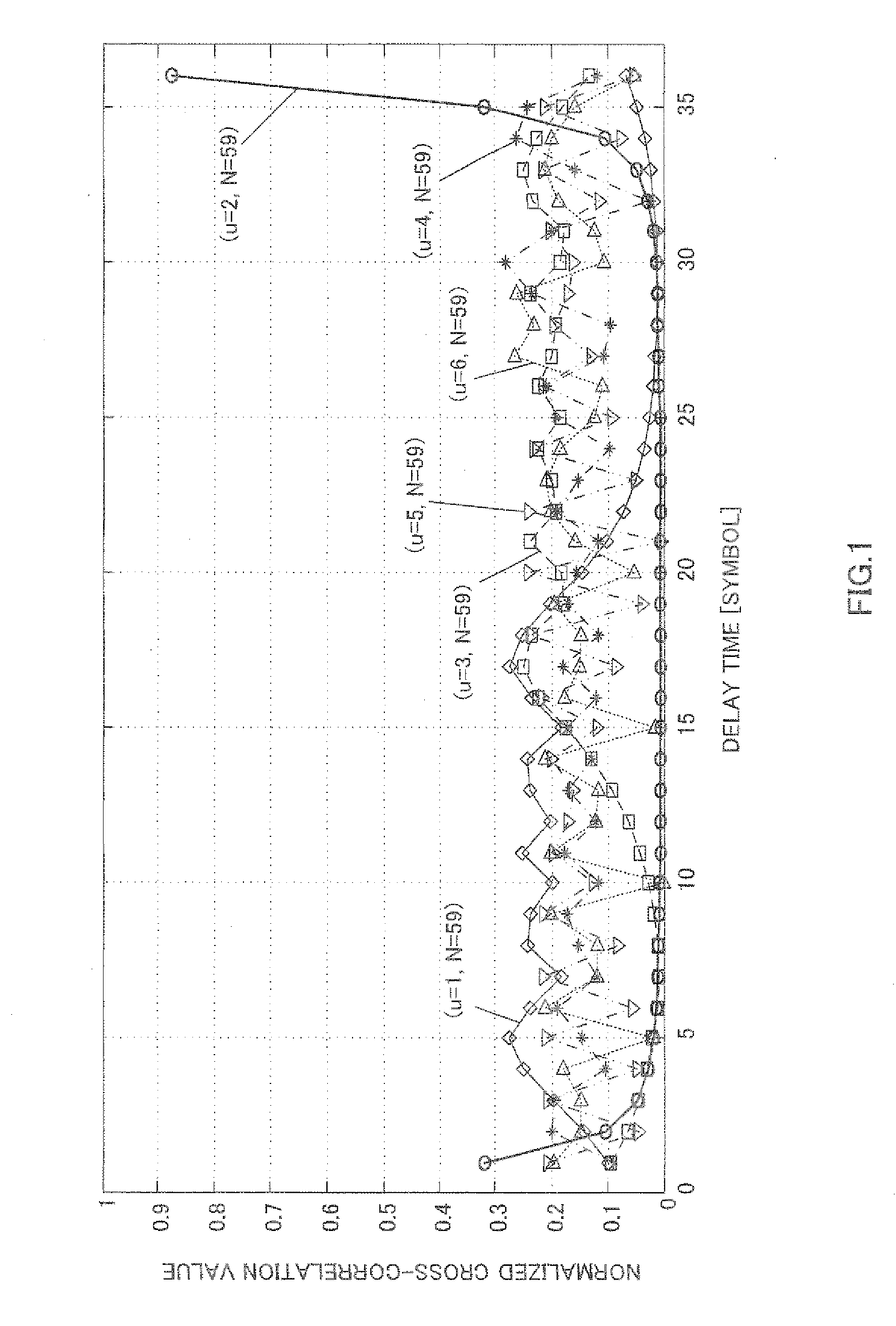
[0102]Here, the same transmission bandwidths (i.e. the same numbers of RBs), sequence lengths N and sequence groups are used as transmission bandwidths (i.e. the numbers of RBs), sequence lengths N and sequence groups shown in FIG. 11 of Embodiment 1. Further, here, when the difference in u / N between ZC sequences is equal to or more than 0.05 (the cross-correlation characteristics shown in FIG. 8 are equal to or less than 0.7), it is assumed that the cross-correlation between the ZC sequences is low.

[0103]...


PUM


Abstract

A wireless communication terminal apparatus wherein the occurrences of inter-sequence interferences between a reference signal preceding a sequence hopping and a reference signal following the sequence hopping can be reduced so as to improve the randomizing effect achieved by the sequence hopping. In this apparatus, a sequence number deciding part (105) has a table in which the sequence lengths of Zadoff-Chu sequences used for reference signals are associated with the sequence numbers of Zadoff-Chu sequences used for reference signals of a slot #1 and with the sequence numbers of Zadoff-Chu sequences used for reference signals of a slot #2. In accordance with a sequence length according to a transmission bandwidth received from a decoding part (104), the sequence number deciding part (105) refers to the table to decide the sequence number of a Zadoff-Chu sequence. In the table of the sequence number deciding part (105), different hopping amounts are provided to a plurality of slot-#2-specific Zadoff-Chu sequences having different sequence lengths.

Description

TECHNICAL FIELD[0001]The present invention relates to a sequence hopping method, a radio communication terminal apparatus and a radio communication base station apparatus.BACKGROUND ART[0002]In a mobile communication system, a reference signal (RS) is used for uplink or downlink channel estimation. In a radio communication system represented by a 3GPP LTE system (3rd Generation Partnership Project Long Term Evolution), a Zadoff-Chu sequence (hereinafter “ZC sequence”) is adopted as a reference signal that is used in uplink. Reasons that a ZC sequence is adopted as a reference signal include a uniform frequency characteristic, and good auto-correlation and cross-correlation characteristics. A ZC sequence is a kind of CAZAC (Constant Amplitude and Zero Auto-correlation Code) sequence and its time-domain representation is expressed by following equation 1,(Equation1)fr(k)={exp{-j2πrN(k(k+1)2-pk)},whenNisodd,k=0,1,…,N-1exp{-j2πrN(k22+pk)},whenNiseven,k=0,1,…,N-1[1]where, “N” is the sequ...

Claims


Application Information

Patent Timeline
IPC IPC(8): H04W40/00H04B1/713H04J13/00H04J13/16H04J13/22
CPCH04B1/7143H04J13/22H04J13/0062
Inventor IWAI, TAKASHIIMAMURA, DAICHIOGAWA, YOSHIHIKOFUTAGI, SADAKIMATSUMOTO, ATSUSHITAKATA, TOMOFUMI
Owner PANASONIC CORP
Learn More