Circuit module and electronic equipment using the circuit module

a circuit module and circuit technology, applied in the direction of printed circuits, printed circuit non-printed electric components association, printed circuits, etc., can solve the problems of resin pouring hole incurred and poor appearance, and achieve the effect of high strength

Inactive Publication Date: 2010-10-28
PANASONIC CORP
View PDF24 Cites 6 Cited by
  • Summary
  • Abstract
  • Description
  • Claims
  • Application Information

AI Technical Summary

Benefits of technology

[0063]In the above construction, the two surfaces of the resin and the turned-back portion are joined together, so that the joining strength increases, and there can be provided the circuit module which is of the thin type and has the high strength.
[0064]Furthermore, the through hole is formed at the region of the turned-back portion exposed from the resin, and therefore a cavity within the turned-back portion (within the U-shaped portion), which is due to expansion of residual gas, can be eliminated, and besides the development of a convex portion formed on the upper surface of the resin by a cavity formed in the resin by gas moved from the interior of the turned-back portion into the resin and also the development of a crater-like irregularity portion formed on the upper surface of the resin portion when gas within the frame passes to the upper surface of the resin can be suppressed.

Problems solved by technology

In the above structure, the resin can be filled relative to a solder ball at a lower surface of the package (to be connected to the motherboard) from all sides of the periphery, and therefore the resin is directly filled and sealed in the connecting portion between the solder ball and the motherboard at which a defective connection due to separation becomes a problem in the BGA type IC package.
In the above structure, the viscosity of the resin which can be used is limited, and unless the resin has a certain degree of viscosity, the flowing of the resin from a resin pouring hole is incurred, which becomes the cause of flashes.
On the other hand, when the viscosity is high, smoothness after curing is lowered, and there is encountered a problem that the appearance becomes poor.

Method used


Image

  • Circuit module and electronic equipment using the circuit module
  • Circuit module and electronic equipment using the circuit module
  • Circuit module and electronic equipment using the circuit module

Examples


embodiment 1

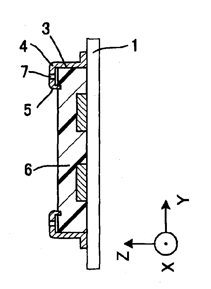
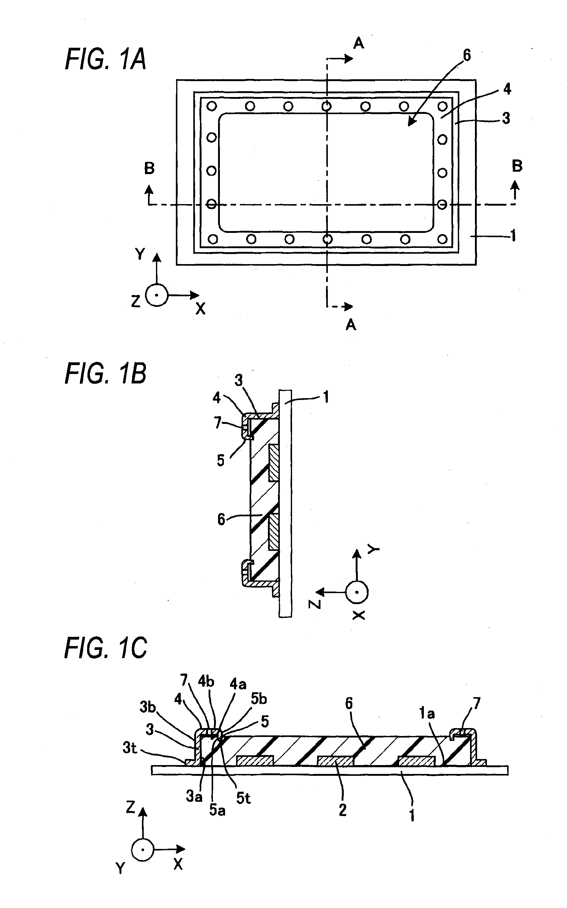
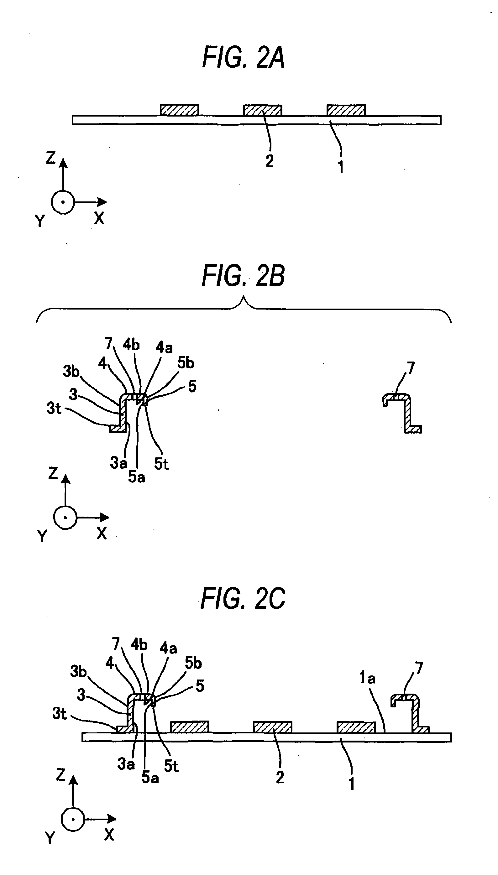
[0105]A circuit module according to Embodiment 1 of the present invention is used in a portable terminal serving as a portable electronic equipment, and is, as shown in FIGS. 1A to 1C, characterized in that the circuit module includes a circuit board 1 having a wiring pattern (not shown) including at least one external connection terminal (not shown), a plurality of electronic parts 2 mounted on one face 1a of the circuit board 1, a tubular body 3 provided in an upstanding manner on the face 1a so as to surround these electronic parts 2 such that part of an inner surface 3a of the tubular body 3 disposed near to a first tube end face 3t is joined to the face 1a, a turned-back portion 4 which is provided at an end of the tubular body 3 opposite from the first tube end face 3t, and has a first surface 4a extending continuously from the inner surface 3a of the tubular body 3 in a direction substantially perpendicular to the inner surface 3a and a second surface 4b opposite to the first...

embodiment 2

[0118]Next, Embodiment 2 of the present invention will be described.

[0119]A circuit module according to Embodiment 2 of the present invention is used in a portable terminal serving as a portable electronic equipment, and differs from the above Embodiment 1 in that an end face 3t of a tubular body 3 is joined to a face 1a of a circuit board 1 and that a sealing resin is filled in the whole of an internal space surrounded by an inner surface 3a of the tubular body 3, a first surface 4a of a turned-back portion and a first extension inner surface 5a of an extension portion 5, without forming any air cavity, as shown in FIGS. 3A to 3C. With this construction, a more improved surface smoothness and a thinner design can be achieved.

[0120]Namely, it is characterized in that it comprises the circuit board 1 having at least one external connection terminal (not shown), a plurality of electronic parts 2 mounted on one face 1a of the circuit board 1, the tubular body 3 provided in an upstandin...

embodiment 3

[0125]Next, Embodiment 3 of the present invention will be described.

[0126]A circuit module according to Embodiment 3 of the present invention is used in a portable terminal serving as a portable electronic equipment, and differs from Embodiment 1 only in that the circuit module does not have any through hole 7 as shown in FIGS. 4A to 4C, and the other is formed in a similar manner.

[0127]In this construction, any through hole is not formed in a turned-back portion extending from a tubular body, and by doing so, the improvement of the strength of the turned-back portion 4 and also the improvement of the strength of the whole including the tubular body and an extension portion can be achieved. Furthermore, a magnetic shielding effect achieved by this tubular body surrounding electronic parts 2 is of course enhanced, and also a moisture resistance is enhanced since any through hole is not provided.

[0128]Incidentally, when filling a sealing resin, it is sometimes difficult to pour the se...


PUM


Abstract

A circuit module of the present invention includes a circuit board, a plurality of electronic parts mounted on one face of the circuit board, a tubular body provided in an upstanding manner on the face in surrounding relation to the electronic parts, a turned-back portion turned back inwardly at a predetermined height position of the tubular body, and a resin portion formed by a sealing resin which is filled in the tubular body to a height reaching a distal end of the turned-back portion such that the resin covers at least part of the electronic parts. With this construction, the two surfaces of the sealing resin and the turned-back portion are joined together, so that the joining strength increases, and there can be provided the circuit module which is of the thin type and has a high strength. Further, through holes are provided at a region of the turned-back portion exposed from the sealing resin, and therefore a cavity within the turned-back portion (within a U-shaped portion), which is due to expansion of residual gas, can be eliminated, and besides the development of a convex portion formed on the upper surface of the resin by a cavity formed in the resin by gas moved from the interior of the turned-back portion into the resin and also the development of a crater-like irregularity portion formed on the upper surface of the resin portion when gas within the frame passes to the upper surface of the resin can be suppressed.

Description

TECHNICAL FIELD[0001]The present invention relates to a circuit module and an electronic equipment using the same, and more particularly to a circuit board in which a plurality of electronic parts are mounted on (attached to) a board on which a circuit pattern comprising wiring conductors is formed, and a frame body is mounted on a substrate in surrounding relation to each electronic part and also to an electronic equipment (having portability), such as a portable phone and a portable communication terminal, using the same.BACKGROUND ART[0002]A circuit board used in a portable terminal such as a portable phone comprises a substrate on which a circuit pattern is formed, and a plurality of electronic parts mounted such that terminal portions thereof are fixed to the circuit pattern through solder.[0003]Also, in recent years, in such a circuit board, there has been proposed a structure in which by providing a reinforcing frame which covers the periphery and upper surface of an IC packa...

Claims


Application Information

Patent Timeline
Patent Type & Authority Applications(United States)
IPC IPC(8): H05K1/18
CPCH05K3/284H05K2203/1316H05K2201/2018
Inventor INOUE, KATSUHIROSASAKI, SATOSHI
Owner PANASONIC CORP
Why Eureka
Try Eureka