
Electromagnetic actuator having permanent magnets placed in the form of a v in an electromagnetically optimized arrangement

a technology of electromagnetic optimization and actuator, applied in the direction of non-mechanical valves, magnetic bodies, machines/engines, etc., can solve the problems of assembly problems, weakening of laminations, etc., and achieve the effect of low risk of short circuit between the support part and the end par

Inactive Publication Date: 2010-10-28
VALEO SYST DE CONTROLE MOTEUR
View PDF15 Cites 9 Cited by
  • Summary
  • Abstract
  • Description
  • Claims
  • Application Information

AI Technical Summary

Benefits of technology

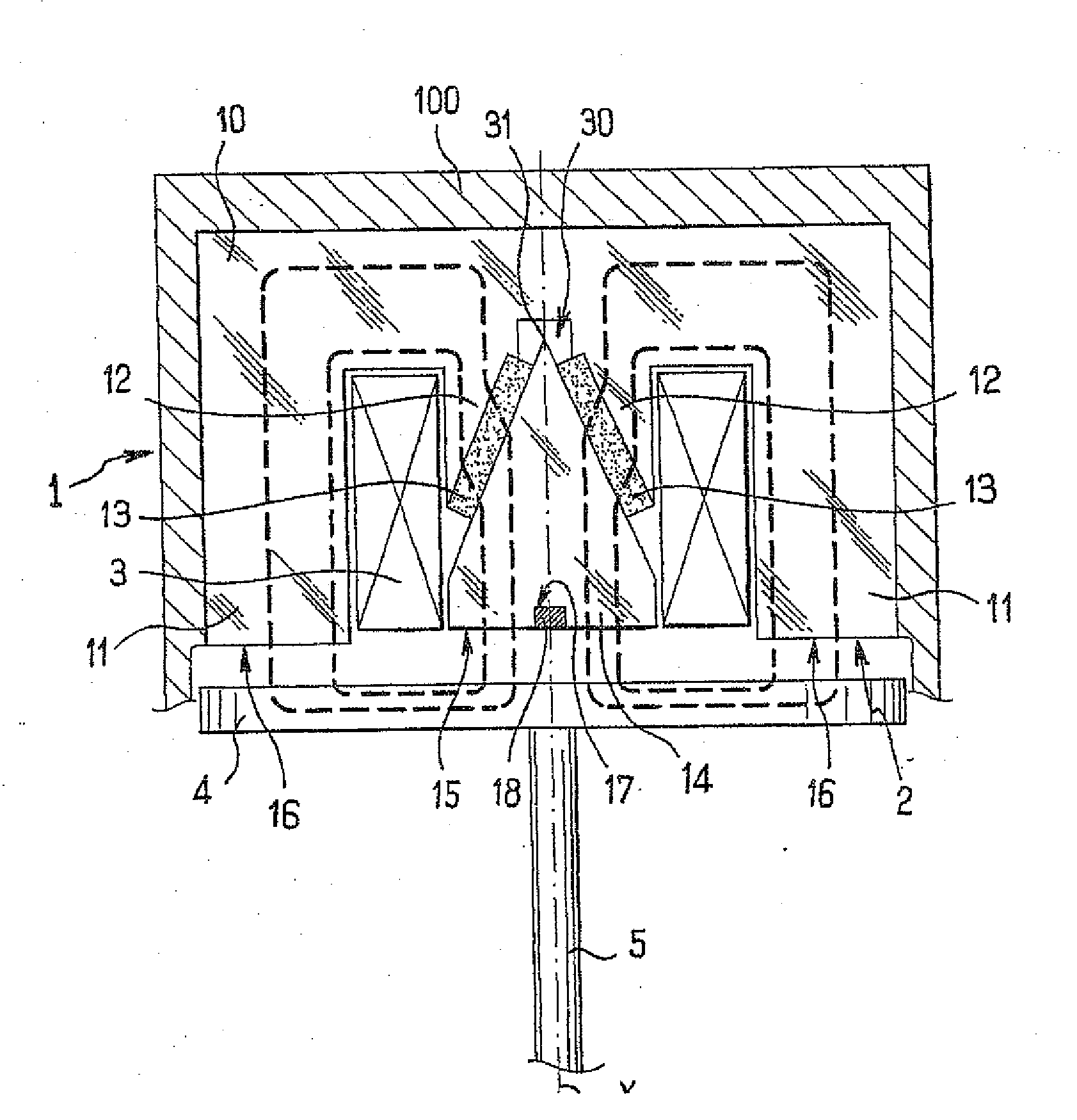
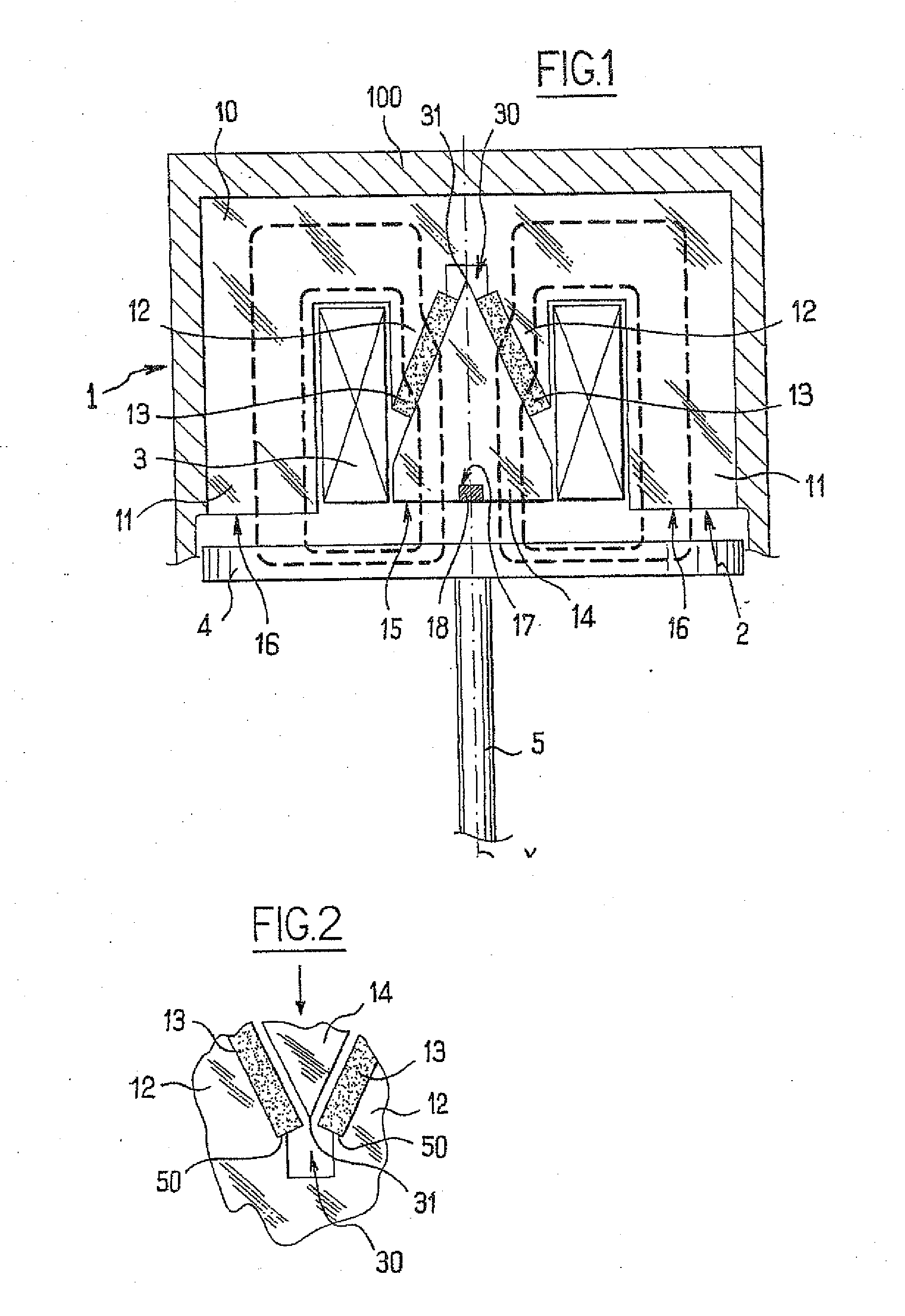
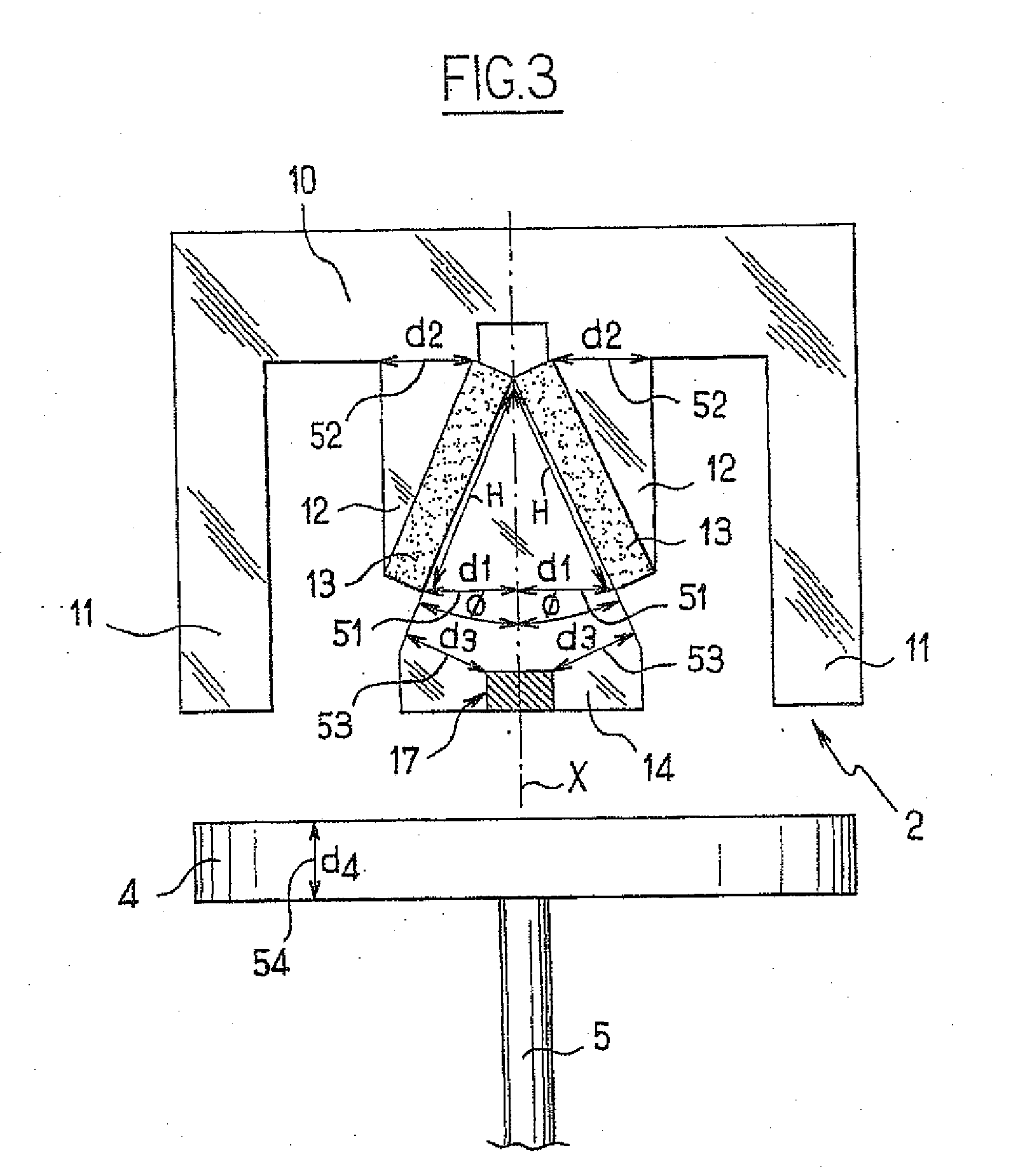
[0006]Thus, the core is separated into a main part, incorporating the part for supporting the magnets, the access to which, for positioning the permanent magnets, is completely free, and an end part, which is attached to the magnets placed on the support part so as to lie above them, the end part being centered by itself on the V formed by the permanent magnets and having no contact with the support part so that the risk of a short circuit between the support part and the end part is very low.
[0007]The sufficient area of the sections of the core or of the armature furthermore avoids any saturation by the flux of the permanent magnets, thereby helping to optimize the electromagnetic efficiency of the actuator.

Problems solved by technology

However, such an arrangement means that the laminations of the core have to be cut so as to allow the magnets to be inserted, thereby mechanically weakening the laminations and posing assembly problems.

Method used


Image

  • Electromagnetic actuator having permanent magnets placed in the form of a v in an electromagnetically optimized arrangement
  • Electromagnetic actuator having permanent magnets placed in the form of a v in an electromagnetically optimized arrangement
  • Electromagnetic actuator having permanent magnets placed in the form of a v in an electromagnetically optimized arrangement

Examples


Embodiment Construction

[0012]As shown in FIG. 1, the electromagnetic actuator of the invention comprises an electromagnet 1 with a core 2 and a coil 3. The electromagnet 1 exerts an electromagnetic force in a controlled manner on an armature 4 integral with a pushrod 5 that can move along the X axis.

[0013]Such an actuator is, for example, used to actuate an internal combustion engine valve, the actuator being placed in such a way that the pushrod 5 extends along the sliding axis of the valve. As is known, the actuator includes another electromagnet (not shown) that extends opposite the electromagnet 1 so as to selectively attract the armature 4 in the opposite direction. The end of the pushrod 5 and the end of the valve are returned to each other by opposing springs (not shown) that define an equilibrium position of the pushrod / valve assembly in which the armature extends substantially at mid-path between the two electromagnets.

[0014]The core 2 of the electromagnet 1 has a base 10 from which two lateral b...


PUM

PropertyMeasurementUnit
apex half-angleaaaaaaaaaa
areaaaaaaaaaaa

Abstract

The invention relates to an electromagnetic actuator including an actuating member associated with an armature and able to move under the action of at least one electromagnet, a coil, and a core suitable for channeling a flux of the coil so that the flux closes within the armature, where the core includes a base from which branches extend, including a central branch around which the coil extends, and two permanent magnets which are associated with the core. The two permanent magnets are placed in the central branch of the core in order to form a V, which separates the central branch into two parts so that any section of the core or the armature through which the flux from one or the other of the permanent magnets can pass, has an area large enough to prevent saturation by this flux.

Description

[0001]The invention relates to an electromagnetic actuator having permanent magnets arranged in the form of a V in an electromagnetically optimized arrangement.BACKGROUND OF THE INVENTION[0002]Document FR 2 865 238 discloses an electromagnetic actuator having an actuating member associated with an armature that can move under the action of an electromagnet, comprising a coil and a core suitable for channeling the flux of the coil so as to form a return path in the armature, the core having a base from which branches extend, including a central branch around which the coil extends. The electromagnet comprises two permanent magnets which are incorporated into the core in such a way that the latter channels the flux of the permanent magnets so as to form a return path in the armature, the flux of the coil passing through the magnets. In one of the embodiments illustrated in that document, the permanent magnets are placed obliquely in the lateral branches of the core, thereby making it ...

Claims


Application Information

Patent Timeline
Patent Type & Authority Applications(United States)
IPC IPC(8): H01F7/16F01L9/20
CPCH01F7/1646F01L9/04F01L9/20H01F7/16
Inventor TALON, EMMANUEL
Owner VALEO SYST DE CONTROLE MOTEUR
Learn More