
Touch screen panel and touch display device

a touch screen panel and touch display technology, applied in the field of touch display technologies, can solve the problems of increasing the thickness of the module, reducing the light transmittance, and increasing the manufacturing cost, so as to reduce the risk of short circuit in the touch screen panel

Inactive Publication Date: 2017-03-16
BOE TECH GRP CO LTD +1
View PDF4 Cites 1 Cited by
  • Summary
  • Abstract
  • Description
  • Claims
  • Application Information

AI Technical Summary

Benefits of technology

The present patent provides a touch screen panel and touch display device to reduce the risk of short circuits in the touch screen panel and ensure good display effects. The panel includes several isolation electrodes arranged between adjacent touch electrodes, which are insulated from each other. This prevents short circuits from occurring between touch electrodes and adjacent isolation electrodes during production, reducing the risk of damage to the touch screen.

Problems solved by technology

As a result, the Add on Mode touch panel has disadvantages such as higher manufacture cost, lower light transmittance and greater module thickness.
However, since the light transmittance of ITO is not 100% and there is a difference between the refractive index of the touch electrodes and that of a base substrate, accordingly there will be a visual difference between the touch electrodes and the gaps therebetween, which makes patterns of the touch electrodes recognizable by naked eyes.
However, as the gap widths between the touch electrodes decrease, the risk for short circuits between the touch electrodes during production will increase.
Therefore, even if a touch electrode and an adjacent isolation electrode are short-circuited during production, such a short circuit will only integrate the isolation electrode into part of the touch electrode while the isolation electrode is still insulated from other touch electrodes, since the isolation electrode is isolated from both other isolation electrodes and other touch electrodes.

Method used


Image

  • Touch screen panel and touch display device
  • Touch screen panel and touch display device
  • Touch screen panel and touch display device

Examples


Embodiment Construction

[0030]The specific implementations of the touch screen panel and the touch display device provided in the embodiments of the present disclosure are described in detail as follows with reference to the drawings.

[0031]Sizes and shapes for each region in the drawings do not reflect the real ratios, but instead, they are only provided for illustrating contents of the present disclosure.

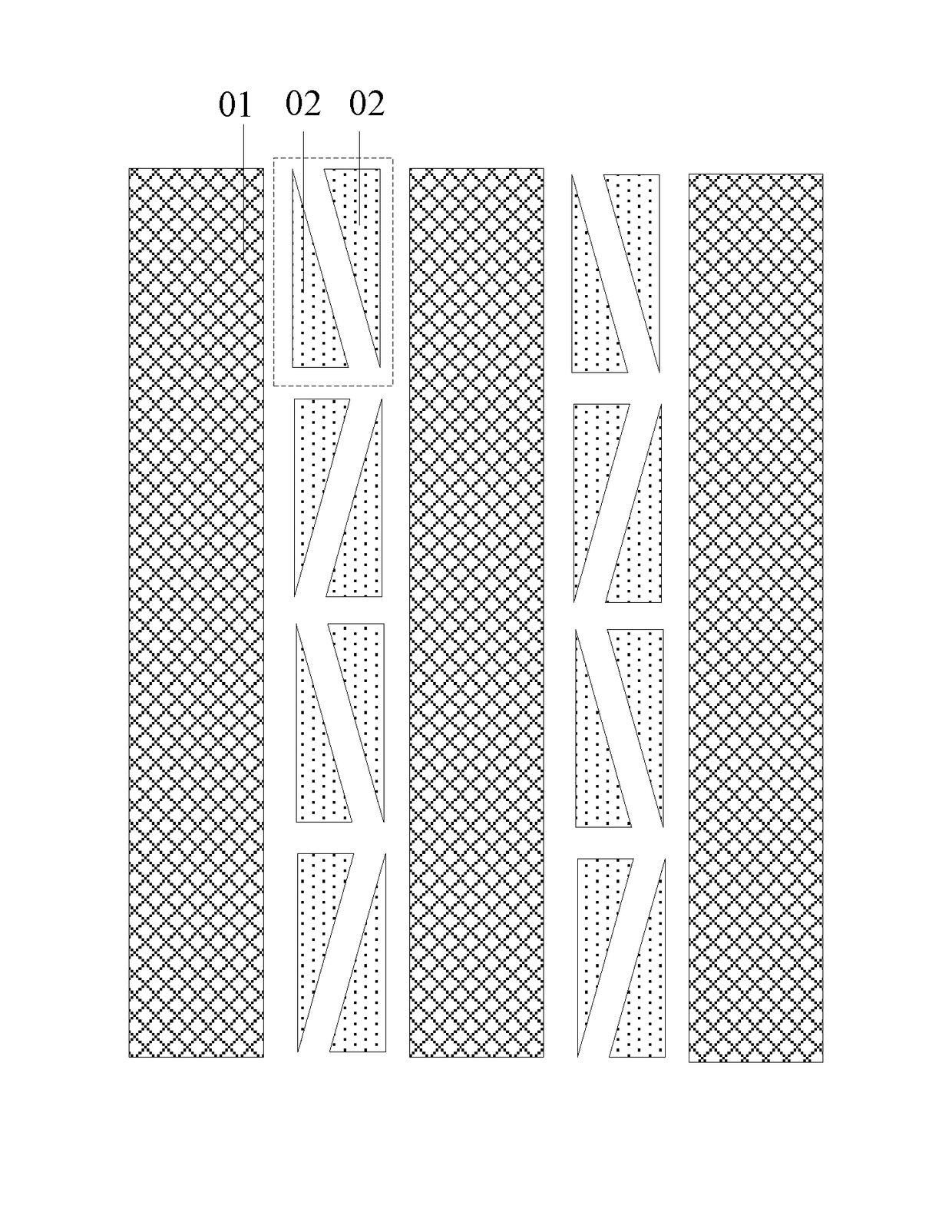
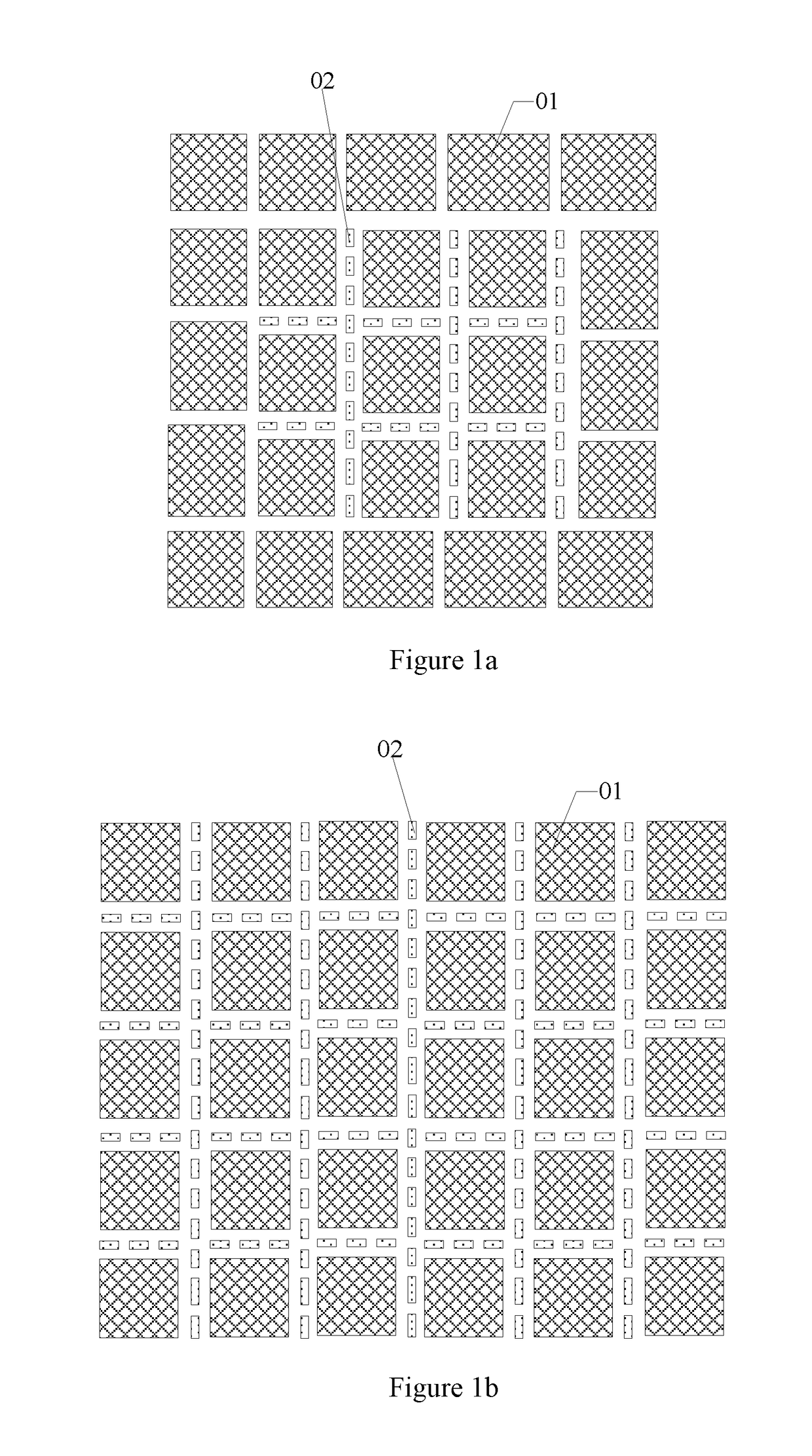
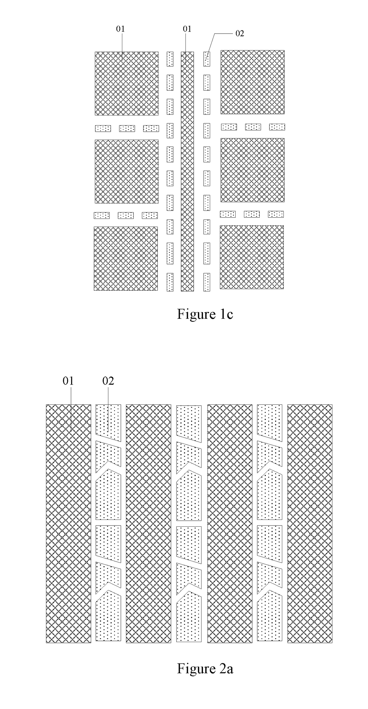
[0032]A touch screen panel is provided in the embodiments of the present disclosure. As shown in FIGS. 1a and 1b, the touch screen panel comprises several touch electrodes 01 arranged in a same layer and being mutually independent. A plurality of mutually independent isolation electrodes 02 are arranged at least in gaps between parts of adjacent touch electrodes 01. The isolation electrodes 02 and the touch electrodes 01 are arranged in a same layer and insulated from each other.

[0033]According to the touch screen panel provided in the embodiments of the present disclosure, several isolation electrodes ar...


PUM

PropertyMeasurementUnit
gap widthsaaaaaaaaaa
widthsaaaaaaaaaa
widthsaaaaaaaaaa

Abstract

The present disclosure relates to a touch screen panel and a touch display device. Several isolation electrodes are arranged in gaps between adjacent touch electrodes, and the isolation electrodes and the touch electrodes are insulated from each other. Therefore, even if a touch electrode and an adjacent isolation electrode are short-circuited during production, such a short circuit will only integrate the isolation electrode into part of the touch electrode while the isolation electrode is still insulated from other touch electrodes, since the isolation electrode is isolated from both other isolation electrodes and other touch electrodes. In this way, the risk of short circuits in the touch screen panel will be greatly reduced.

Description

RELATED APPLICATIONS[0001]The present application claims the benefit of Chinese Patent Application No. 201510194980.8, filed on Apr. 22, 2015, the entire disclosure of which is incorporated herein by reference.FIELD[0002]The present disclosure relates to the field of touch display technologies, and in particular to a touch screen panel and a touch display device.BACKGROUND ART[0003]With rapid development of display technologies, touch screen panels have gradually pervaded people's lives. At present, according to composition structures, touch screen panels can be divided into: Add on Mode touch panels, On Cell touch panels and In Cell touch panels. An Add on Mode touch panel is a liquid crystal display having a touch function, which is formed by separately producing a touch screen panel and a liquid crystal display (LCD) and then bonding them together. As a result, the Add on Mode touch panel has disadvantages such as higher manufacture cost, lower light transmittance and greater mod...

Claims


Application Information

Patent Timeline
Patent Type & Authority Applications(United States)
IPC IPC(8): G06F3/041G02F1/1333G06F3/044
CPCG06F3/0412G02F1/13338G06F3/044G06F3/0443G06F3/0448G06F3/041
Inventor PENG, CHUANZHANG, FENGKIM, HWANGLU, YOUQIANG
Owner BOE TECH GRP CO LTD
Learn More