
Adaptable Rugged Terrain Cart

a cart and rugged technology, applied in the direction of transportation items, vehicular safety arrangements, pedestrian/occupant safety arrangements, etc., can solve the problems of requiring the operator to lift or bear a significant portion of the dead weight of the load, similar prior art designs forgo the provision of a third or additional person, and similar prior art designs forgo the provision of non-human sources of motive power. , to achieve the effect of minimizing the vertical height of the center of mass of the load, easy and comfortable pro

Inactive Publication Date: 2010-10-28
ODLE KIRTLAND LOUIS +1
View PDF24 Cites 14 Cited by
  • Summary
  • Abstract
  • Description
  • Claims
  • Application Information

AI Technical Summary

Benefits of technology

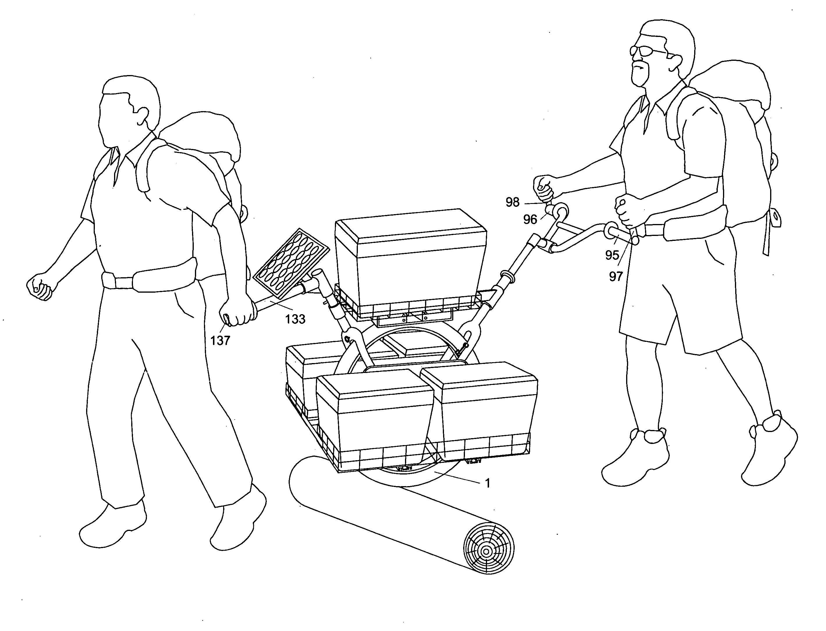
[0010]The present invention comprises a cart, or vehicle, having a single wheel equipped with a treaded tire, supporting a light weight, yet very rigid frame, which is easily and comfortably propelled by one or more persons over long distances of pitched, narrow, rugged or uneven terrain, such as a hiking trail. The design of the vehicle minimizes the vertical height of the center of mass of the load, optimizes ground clearance and width, and balances the center of mass of the load vertically above the axle of the wheel, thereby making the vehicle highly maneuverable and stable under load. The primary operator conveys the vehicle by way of pushing forward on a set of adjustable handlebars mounted at the rear, or back, position. To navigate obstacles blocking the path, ford creeks, or otherwise traverse surfaces over which the wheel is ineffective, a retractable front mounted supplemental boom allows a second person to assist the operator in lifting and carrying the vehicle. An attachment point coupling allows connection of various sources of supplemental motive power while minimizing the induction of lateral forces. An integral, highly efficient brake allows the operator to variably retard or completely halt the vehicle while in motion, or lock the brake for parking on steep grades. Easily interchangeable modular load bearing platform and fixture assemblies allow the capacity and configuration of the vehicle to be altered quickly without tools, thereby allowing the vehicle to easily adapt to the requirements of the loads to be transported. The axle and wheel assembly may be mounted to the frame in either a fixed rigid, or a decoupled, compressionally loaded manner. The vehicle may also be equipped with an accurate odometer, and an integral rechargeable electrical system capable of receiving, storing, and supplying AC or DC power to support a variety of communication, computing, navigation or other electronic equipment and tools.

Problems solved by technology

Other examples of load bearing devices intended for rugged terrain, of less similar design and more resembling traditional wheel barrows, either pushed ahead of, or pulled behind, the primary operator, do not allow for the continuous bearing of the load vertically above the center of the bearing axle of the wheel(s), thereby requiring the operator to lift or bear a significant portion of the dead weight of the load, in addition to applying motive and steering forces to convey the load.
All similar prior art designs forgo the provision of a third or additional persons to assist in conveying the vehicle.
All similar prior art designs forgo the provision to attach non-human sources of motive power, such as a dog team, small pack animal, etc.
In either case, the prior art is designed without the ability to interchange, alter, or otherwise significantly reconfigure the orientation and nature of their respective load bearing surfaces, platforms and fixtures, thereby precluding the ability of each vehicle's design to adapt to widely differing load contents and conditions, and so reducing their overall usefulness.
All prior art vehicles employing multiple wheels, such as dual wheels being laterally oriented, as seen in Hamblin, are inherently less able to remain vertically oriented on trail surfaces that are not level, requiring additional exertion from the operator to keep the vehicle upright and the load intact.
All prior art vehicles employing dual wheels that are sequentially oriented, that is, an inline front and a rear wheel, as seen in Woods, suffer from the inability to turn sharply, or pivot on a single point, to the left or right, and so are less able to negotiate acutely angled turns, often at steep grades, which are common on trails.
Both orientations of dual wheeled vehicles reduce the maneuverability of the examples, and increase the exertion required by the operator(s) while conveying the load, as well as increasing the possibility for slipping, falling, and tipping over, thereby risking injury to the operator, or damage to the load contents.

Method used


Image

  • Adaptable Rugged Terrain Cart
  • Adaptable Rugged Terrain Cart
  • Adaptable Rugged Terrain Cart

Examples


Embodiment Construction

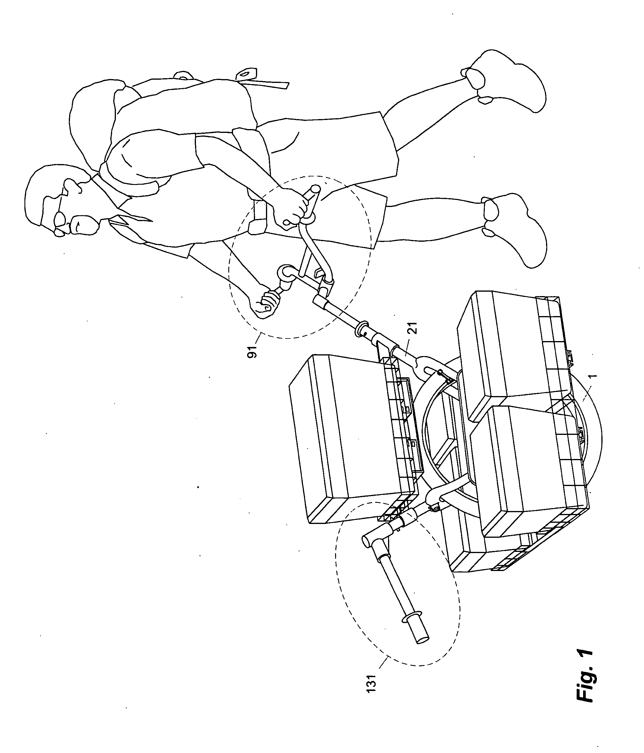
[0033]The invention is generally described as a cart for transporting equipment and provisions over rough, rugged or uneven terrain, such as a trail. The invention's primary mode of operation is shown in FIG. 1. with the primary operator positioned at the back, and pushing the device, whose center of mass is balanced and completely borne by the wheel (1) and frame (21), by being positioned along the vertical line passing through the middle of the axle (11).

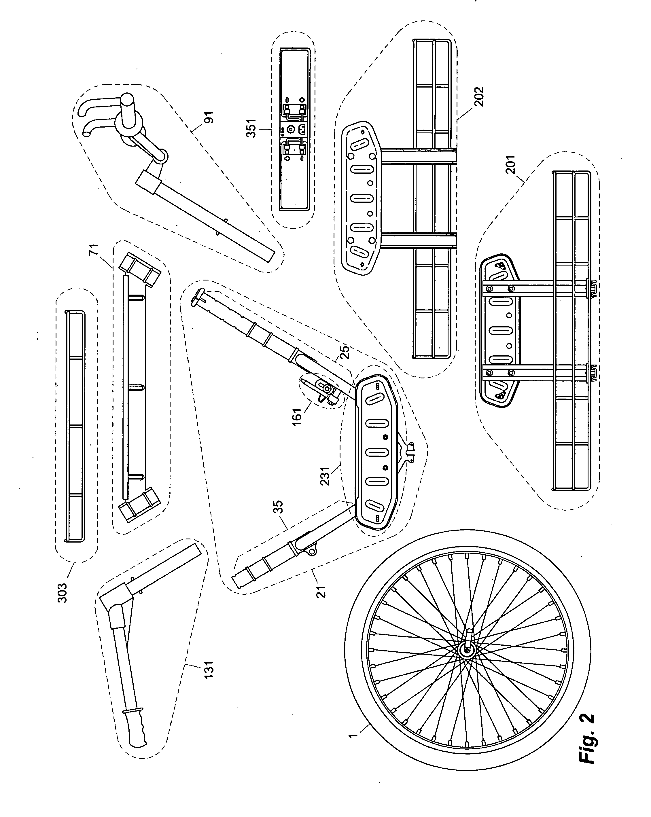
[0034]As seen in FIG. 2, the invention is comprised of several core assemblies with each assembly itself being composed of subsidiary members and components. The invention has a single wheel (1), which is attached to a rigid frame assembly (21), lower portions of which form a wheel housing, and upper portions of which provide structures for the attachment of an assembly intended for steering (91) and an assembly intended for assistance in lifting or portage (131). A removable horizontal truss member (71) couples between location p...


PUM


Abstract

The current invention is a non motorized cart for use on rugged terrain, operated by one or more persons, comprising a single wheel with a brake attached to the wheel housing of a rigid frame. The frame additionally comprises a posteriorly positioned primary steering and lifting handgrip, and an anteriorly positioned supplementary assistance lifting handgrip. The frame additionally provides multiple detachable connections for various interchangeable load bearing platforms, which can be easily interchanged in the field, without tools. The frame additionally provides an attachment point for supplemental sources of motive power. Additional features include an electronic odometer and a self contained electrical storage system.

Description

BACKGROUND OF THE INVENTION[0001]Numerous examples exist of similar single wheeled carts intending to ease the burden of transporting relatively heavy equipment, provisions, etc. over hiking trails and other rugged terrain. Among these are U.S. Pat. Nos. 3,456,959 to Thomas Hemphill; 4,055,354 to Donald M. Sharpe; 4,063,744 to Charles Fraser; 4,171,139 to Edwin Cockram; 4,444,405 to Dwight Barrus; and 4,869,517 to Philip Smith.[0002]These patents disclose devices utilizing a single wheel, and which employ various fixed, generic load bearing surfaces, and are equipped with a variety of handles, harnesses and yoke attachments used to facilitate propelling and maneuvering the vehicles along rugged terrain by one or two persons. A shared central design feature among these examples is the positioning of the load so as to continuously balance the center of mass vertically above the axle of the wheel thereby minimizing the amount of effort on the part of the operator while in use, and so a...

Claims


Application Information

Patent Timeline
IPC IPC(8): B62B1/12
CPCB62B1/12B62B5/02B62B5/0476B62B5/061B62C1/04B62B2202/12B62B2205/104B62B2301/20B62B5/068B60L50/20B62B5/06
Inventor ODLE, KIRTLAND LOUISODLE, KEITH PRESTON
Owner ODLE KIRTLAND LOUIS
Learn More