
Oil lamp with heat conductive element

a technology of heat conductive elements and oil lamps, which is applied in the field of oil lamps, can solve the problems of not being able to replace the fragrance separately from the oil supply to the wick, and not being able to meet the needs of both meltable fuel and prior art devices,

Inactive Publication Date: 2010-10-28
FIRMENICH SA
View PDF8 Cites 15 Cited by
  • Summary
  • Abstract
  • Description
  • Claims
  • Application Information

AI Technical Summary

Benefits of technology

[0010]ii) the device comprises a reflux protection element lodged across the hole or aperture of the capping piece and shaped so as to entirely cover the capping piece's hole and prevent liquid reflux into the reservoir; and
[0026]Other materials that can be used as the meltable substance are well-known to the skilled person and described in prior documents such as for example U.S. Pat. No. 6,802,707 previously cited. The meltable substance may take any desired shape such as pucks, donuts, balls, pellets, slivers, particulates, wafers, disks, or any other shape that is compatible with the melting plate shape. Particularly attractive shapes are particulate type forms, such as balls and pellets, which make it possible to easily replenish the melted substance upon total consumption of the previous supply. This also facilitates varying the nature of the fragrance over time. Of course, it is also possible to use colored particles which render the device particularly attractive from an esthetic point of view.
[0034]The combustion fuel that feeds the wick and makes it possible to generate the flame may be perfumed, but preferred embodiments of the invention will only contain fragrance in the meltable material contained in the melting place. This advantageously avoids having “burnt” fragrance notes diffused into the devices surroundings.

Problems solved by technology

These prior art devices cannot however accommodate the use of both a meltable fuel and a liquid fuel, arranged as described hereinafter.
This device avoids the severe heating of the fragrance which is typical of burning lamps of a conventional type, but it does not allow replacement of the fragrance separately from the oil supply to the wick.
Moreover, as the fragrance is containing in the wick feeding oil, part of the fragrance is still burned at the wick.

Method used


Image

  • Oil lamp with heat conductive element
  • Oil lamp with heat conductive element
  • Oil lamp with heat conductive element

Examples


Embodiment Construction

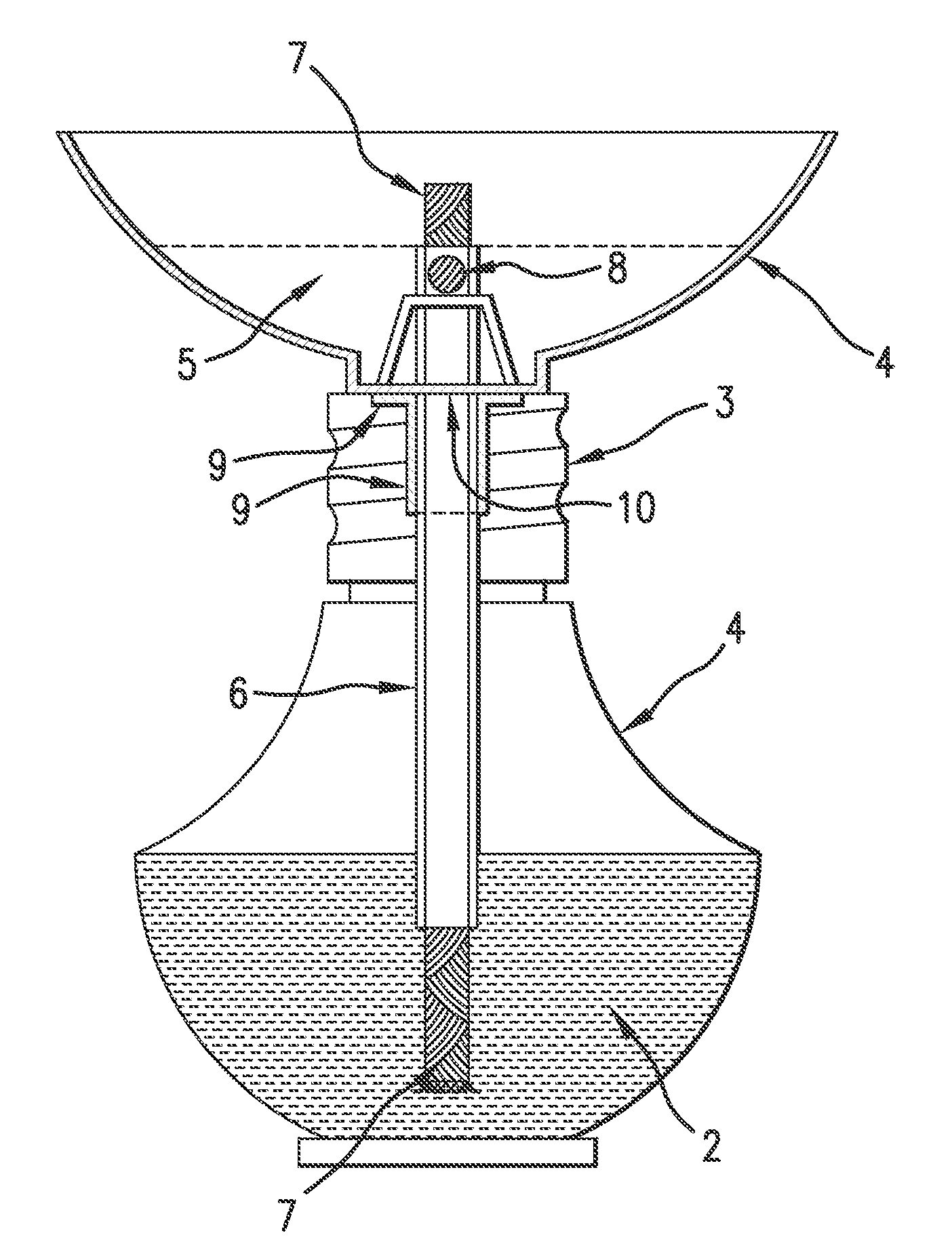
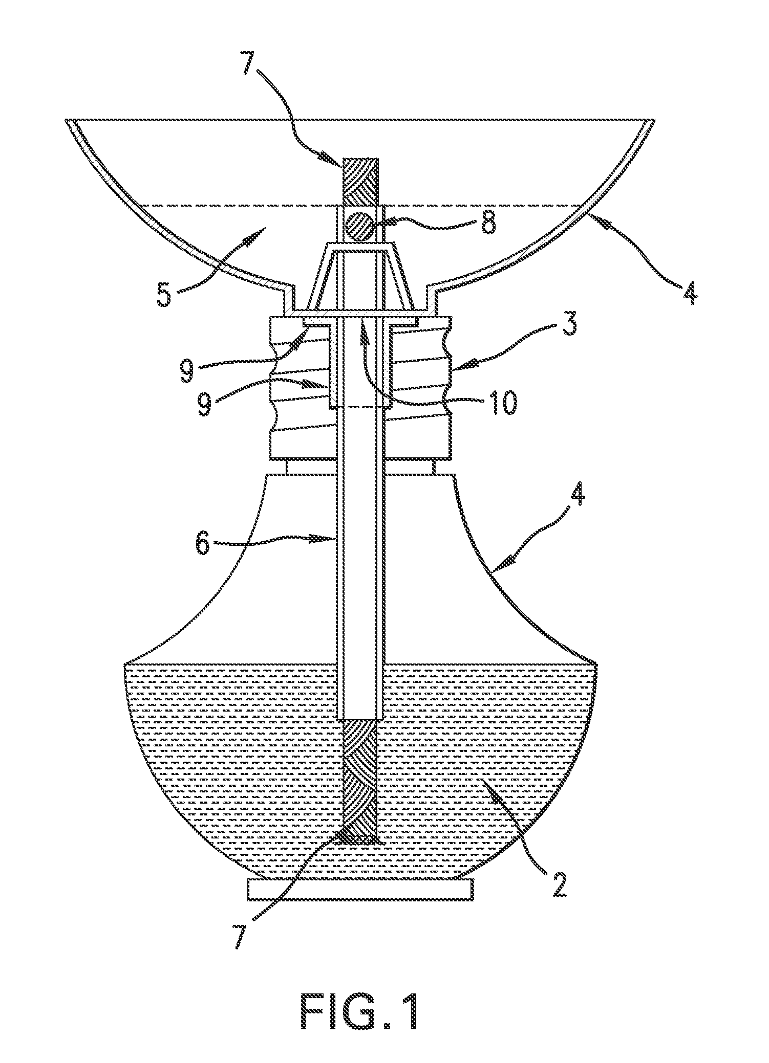
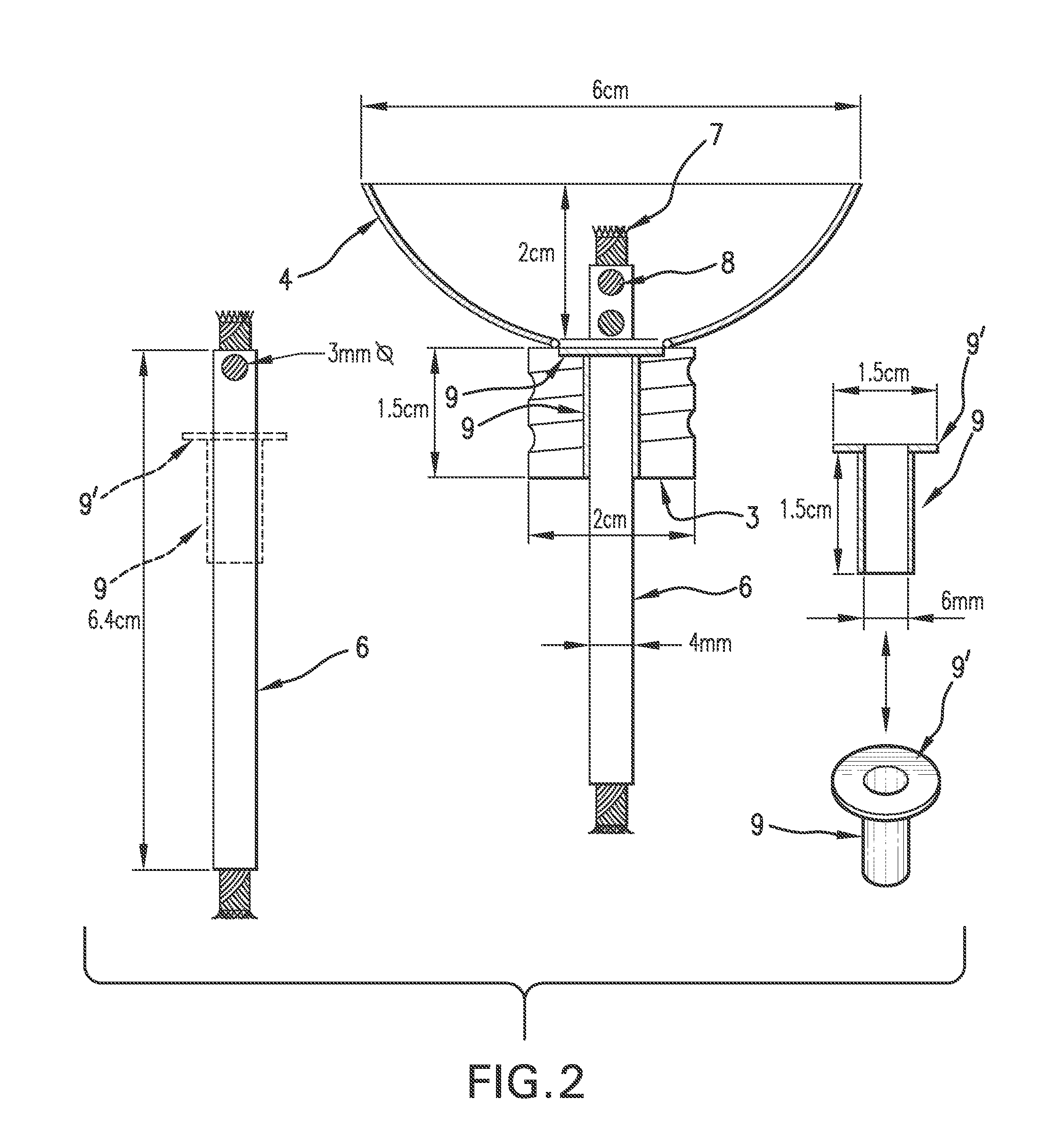
[0044]With reference to FIG. 1, representing an embodiment of the invention, the device comprises a container 1 for a combustion fuel 2, provided with an upper aperture capped by a piece 3. A concave shaped melting plate 4 is lodged on top of the capping piece 3 and contains a melted material 5 carrying a fragrance or other volatile material. A hollow cylindrical tube 6 crosses through an aperture or hole provided in the capping piece 3 so as to extend between the fuel 2 and the upper end of the wick 7 and serves as the supporting or guiding structure for the latter during the combustion. The upper end of the wick 7 provides the lighting flame which also serves as the heat source for maintaining the meltable substance 5 in a continuously melted state and thus diffuses the volatile substance contained in said meltable material into the surroundings.

[0045]The wick holding tube 6 which extends from the bottom of the lamp to the top of the melting plate 4 keeps the wick centralized and ...


PUM

PropertyMeasurementUnit
temperaturesaaaaaaaaaa
depthaaaaaaaaaa

Abstract

The present invention relates to a device generally in the form of an oil lamp and adapted to a dual function of diffusing light and a volatile material. The device includes a fuel and a wick formed of combustible material, and a heat conductive element adapted to receive a gel or solid material capable of melting at the burning temperatures of the device. The material is a carrier for a volatile substance that is released into the atmosphere upon melting of the carrier material. Fragrances are preferred embodiments of the volatile substance. Methods for use of the device in the simultaneous diffusion of light and volatile substances, namely fragrances, are also disclosed.

Description

[0001]This application claims the benefit of application No. 61 / 173,369 filed Apr. 28, 2009.TECHNICAL FIELD[0002]The present invention relates generally to oil lamps of the type that comprise a fluid vessel containing a liquid, gel or solid fuel and a wick formed of combustible material. It concerns more particularly an oil lamp of this type which further comprises a heat conductive element adapted to receive a gel or solid material capable of melting at the burning temperatures of the lamp. Said material is a carrier for a volatile substance that is released into the atmosphere upon melting of the carrier material. Fragrances are preferred embodiments of the volatile substance. Methods for use of the invention's oil lamp in the simultaneous diffusion of light and volatile substances, namely fragrances, are also disclosed.BACKGROUND[0003]The diffusion of volatile substances via vaporization of the latter from a carrier material that is submitted to a heat source is well known from t...

Claims


Application Information

Patent Timeline
Patent Type & Authority Applications(United States)
IPC IPC(8): A61L9/03
CPCA01M1/2088C11C5/00A61L2209/12A61L9/037
Inventor ALLISON, GERALDTRANZEAT, LYSEWILLIAMS, JONATHAN
Owner FIRMENICH SA
Learn More