
Coating composition for antireflection, antireflection film and method for preparing the same

a coating composition and anti-reflection technology, applied in the field of coating compositions for anti-reflection, anti-reflection films and methods for preparing the same, can solve the problems of deteriorating resolution in high-resolution displays, affecting the sharpness of images, and affecting the image quality, so as to achieve excellent anti-reflection characteristics and abrasion resistance, excellent anti-reflection characteristics, and excellent anti-reflection characteristics. good

Inactive Publication Date: 2010-10-21
LG CHEM LTD
View PDF14 Cites 18 Cited by
  • Summary
  • Abstract
  • Description
  • Claims
  • Application Information

AI Technical Summary

Benefits of technology

[0009]In order to solve the above-mentioned problems, an object of the prevent invention is to provide a coating composition for antireflection, in which although the single coating composition is used to form a coating layer by one coating process, phase separation occurs on the coating layer to provide antireflection characteristic and abrasion resistance simultaneously, thereby improving process efficiency and reducing manufacturing cost; an antireflection film manufactured using the coating composition for antireflection; and a method of manufacturing the antireflection film.Technical Solution
[0020]By using the above-mentioned coating composition for antireflection and the method of manufacturing the antireflection film, the present invention can provide an antireflection film including an antireflection layer that has excellent antireflection characteristic and abrasion resistance, in which the antireflection layer is composed of a singe coating layer. Since the antireflection film according to the present invention has excellent abrasion resistance and low refractive characteristic, and can be manufactured by one coating process, it is possible to improve process efficiency and reduce manufacturing cost.

Problems solved by technology

One method causes diffused reflection by using convexo-concave shape on the surface, and the other method causes destructive interference by using a multi-coating design.
However, there have been problems in that resolution deteriorates in a high-resolution display and the sharpness of an image deteriorates due to diffused reflection.
However, since there are problems in that luminance and contrast deteriorate, the light-diffusion film needs to be modified.
However, when an antireflection coating layer is formed on a plastic film, it is not possible to satisfy the abrasion resistance of a display.
However, there is still a problem in that manufacturing cost is increased due to the multi-coating.
However, since the shape and size of the ultrafine particles should be uniform and these particles should be uniformly distributed on the substrate, it is difficult to achieve this method by general coating processes.
Further, since the amount of a binder should be equal to or smaller than a predetermined amount in order to obtain a spherical shape on the surface of the film, there is a problem in that this method is very vulnerable to abrasion resistance.
Further, since the coating thickness should be also smaller than the diameter of the fine particle, it is very difficult to obtain abrasion resistance.

Method used


Image

  • Coating composition for antireflection, antireflection film and method for preparing the same
  • Coating composition for antireflection, antireflection film and method for preparing the same
  • Coating composition for antireflection, antireflection film and method for preparing the same

Examples


example 1

[0105]30 parts by weight of the low refractive-thermosetting material A and 70 parts by weight of the high refractive-UV curable material E were uniformly mixed to prepare a coating composition for antireflection.

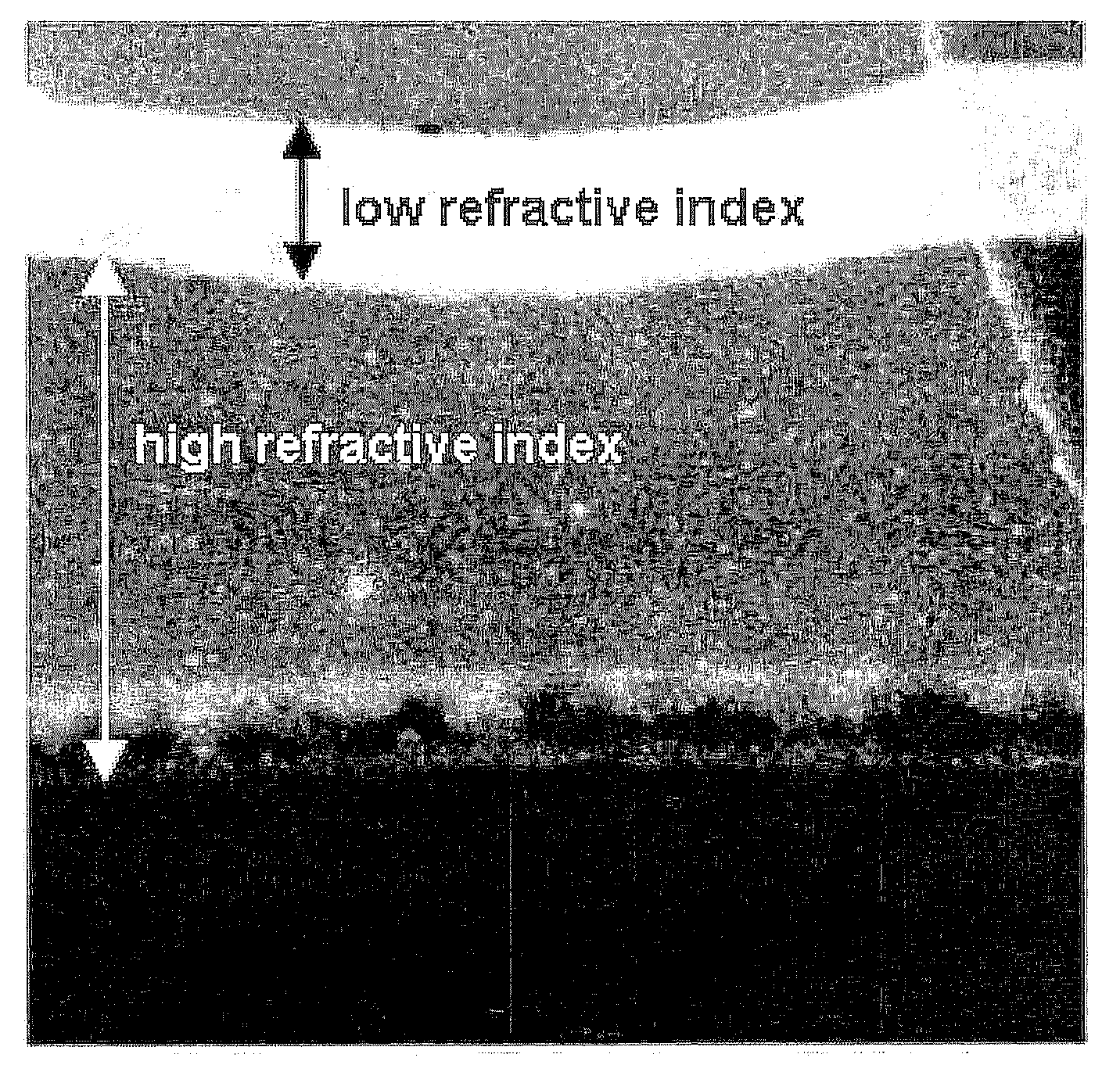
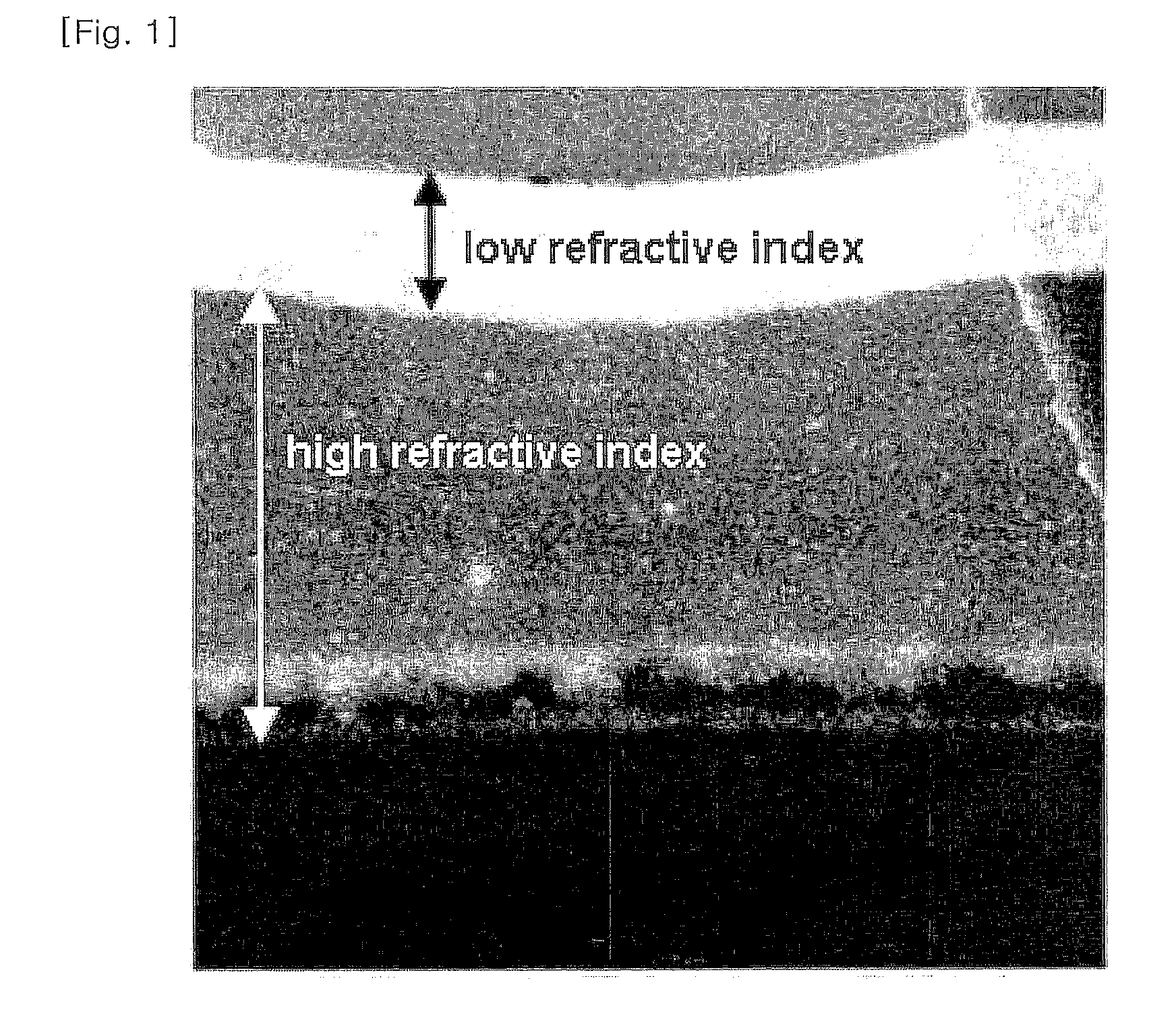
[0106]The prepared composition was applied to a triacetate cellulose film having a thickness of 80 an using a wire bar (No. 5). The film was dried in an oven at 60° C. for 2 min, and cured by UV radiation at a dose of 1 J / cm2, followed by heat curing in the oven at 120° C. for a day. The final coating layer had a thickness of 1 μm, and its cross-section was observed under a transmission electron microscope, shown in FIG. 1.

[0107]With reference to FIG. 1, it was found that the high refractive material layer and the low refractive material layer were separately formed on the substrate in a layer structure. When the layer structure is formed by the materials having different refractive indices, more effective reflectance can be obtained, as compared to a monolayer structure.

example 2

[0108]A film was manufactured in the same manners as in Example 1, except using a material B instead of the material A as a low refractive-thermosetting material.

example 3

[0109]25 parts by weight of the low refractive-thermosetting material C and 75 parts by weight of the high refractive-UV curable material F were uniformly mixed to prepare a compatible mixed solution, resulting in a coating composition.

[0110]The prepared coating composition was applied to a triacetate cellulose film having a thickness of 80 μm using a wire bar (No. 5). The film was dried in an oven at 120° C. for 2 min, and cured by UV radiation at a dose of 200 mJ / cm2, followed by heat curing in the oven at 120° C. for a day. The final coating layer had a thickness of 1 μm.


PUM

PropertyMeasurementUnit
surface energyaaaaaaaaaa
refractive indexaaaaaaaaaa

Abstract

The present invention provides a coating composition for antireflection that includes a low refractive material having a refractive index of 1.2 to 1.45 and a high refractive resin having a refractive index of 1.46 to 2, in which the difference in the surface energy between two materials is 5 mN / m or more; an antireflection film manufactured using the coating composition for antireflection; and a method of manufacturing the antireflection film. According to the present invention, the antireflection film having excellent abrasion resistance and antireflection characteristic can be manufactured using a single composition by one coating process, thereby reducing manufacturing cost.

Description

TECHNICAL FIELD[0001]The present invention relates to a coating composition for antireflection, an antireflection film manufactured using the coating composition for antireflection, and a method of manufacturing the antireflection film. More particularly, the present invention relates to a coating composition for antireflection, in which although a single coating composition containing resins that have a refractive index different from each other is used to form a single coating layer by one coating process, phase separation occurs on the single coating layer, thereby providing antireflection characteristic and abrasion resistance simultaneously; an antireflection film manufactured using the coating composition for antireflection; and a method of manufacturing the antireflection film.[0002]This application claims priority from Korean Patent Application Nos. 10-2007-0115348 and 10-2007-0115329 filed on Nov. 13, 2007, Korean Patent Application No. 10-2007-0115967 filed on Nov. 14, 200...

Claims


Application Information

Patent Timeline
Patent Type & Authority Applications(United States)
IPC IPC(8): G02B5/30F21V9/06B05D3/10C08F2/48B32B27/08
CPCG02B1/111C08F2/48Y10T428/31663
Inventor YUN, HANSIKKIM, HYEMINKIM, BOO KYANGCHANG, YEONG-RAE
Owner LG CHEM LTD
Learn More