
Head assembly for chip mounter

Active Publication Date: 2010-10-21
HANWHA PRECISION MASCH CO LTD
View PDF8 Cites 13 Cited by
  • Summary
  • Abstract
  • Description
  • Claims
  • Application Information

AI Technical Summary

Benefits of technology

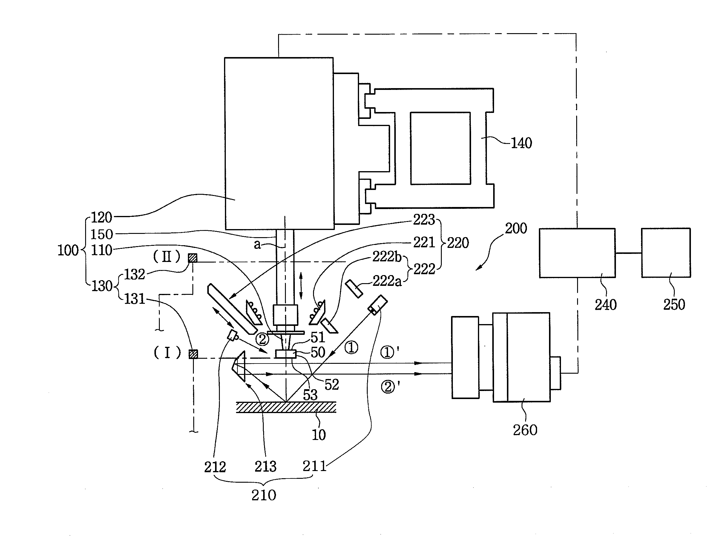
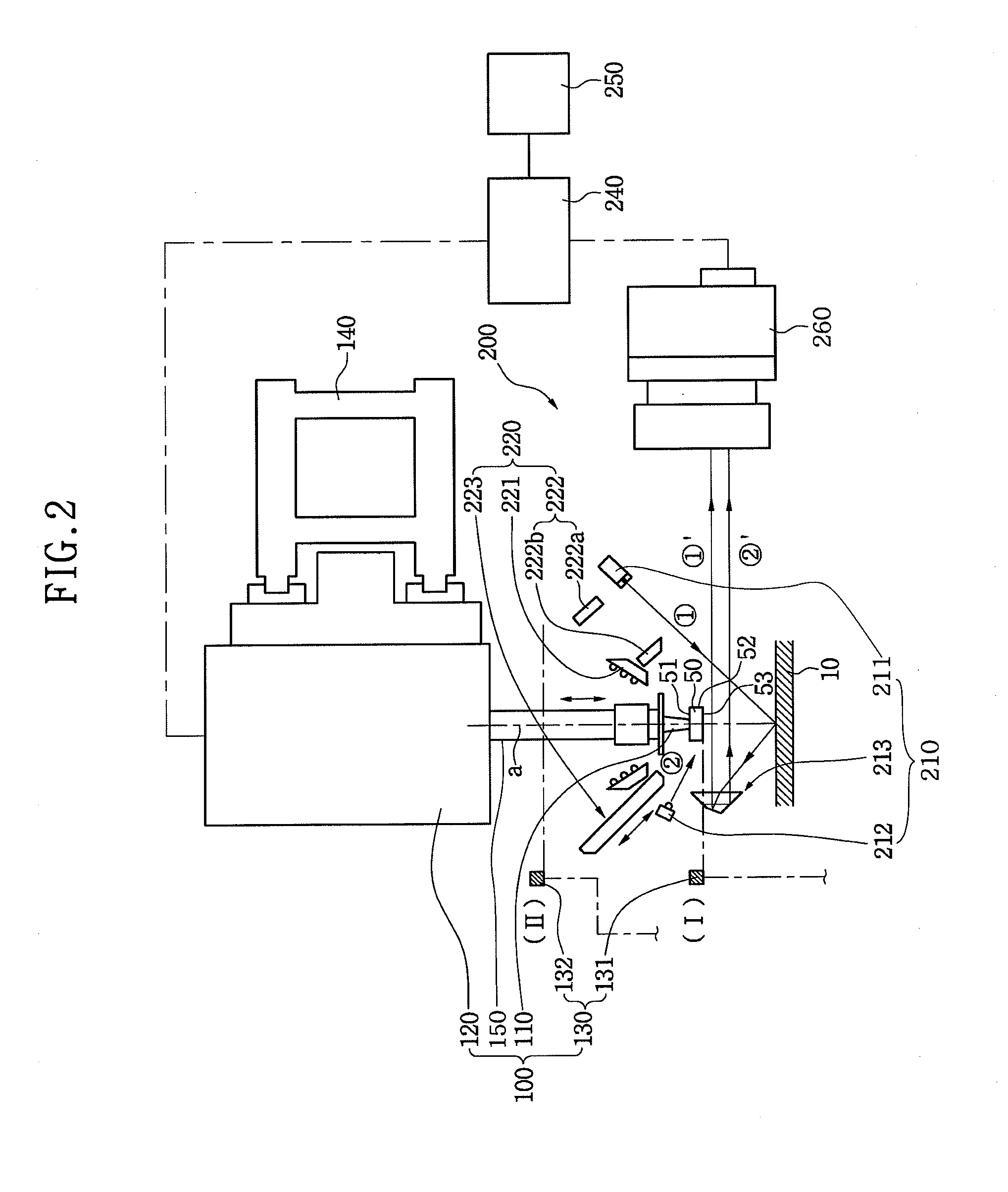
[0013]Exemplary embodiments provide a head assembly for a chip mounter capable of recognizing presence of an electronic component sucked by a nozzle and posture of the electronic component based on a lower surface and side surfaces of the electronic component, and recognizing a distance between the nozzle and a mounting position of a PCB on which the electronic component is mounted.

Problems solved by technology

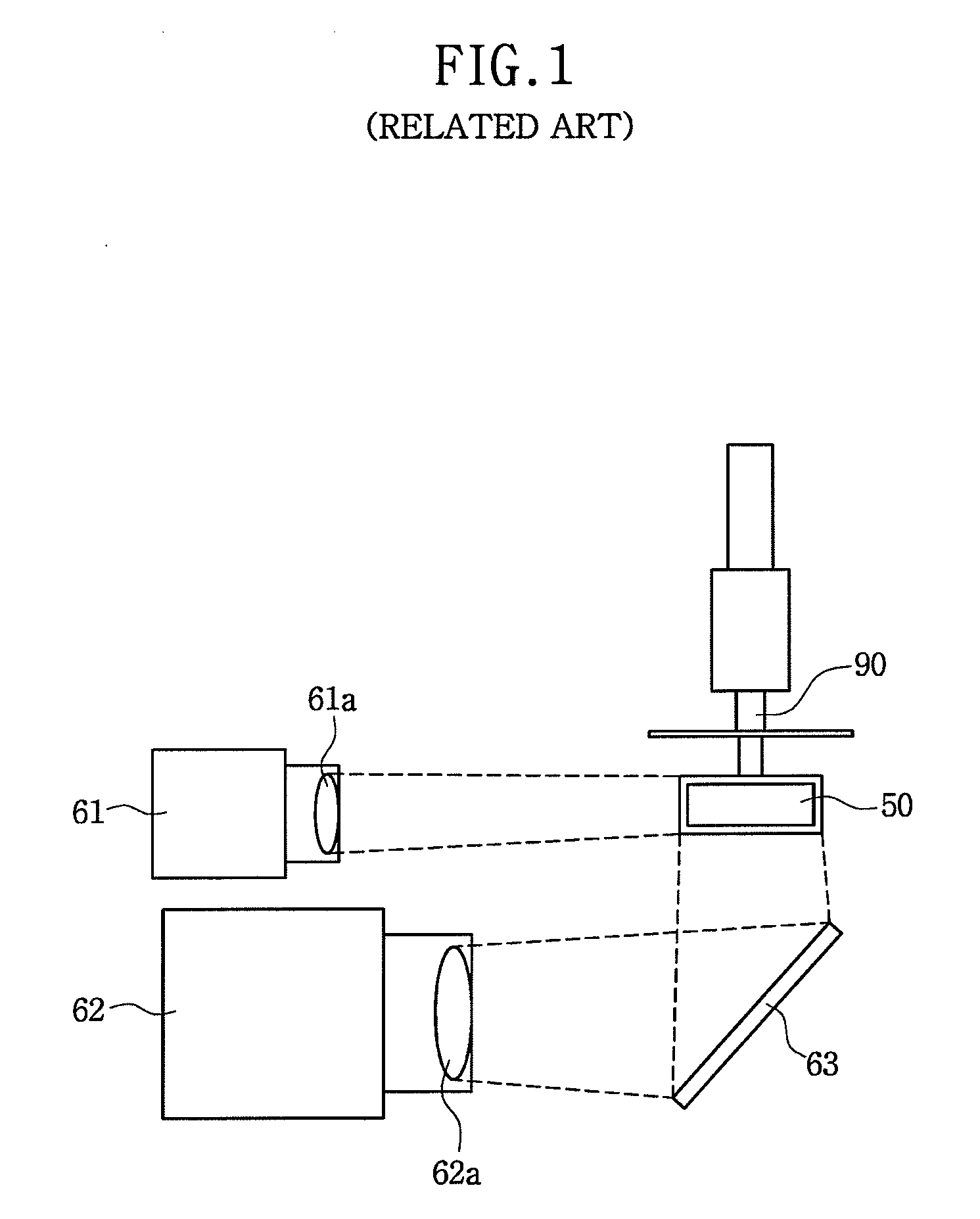
In addition, since the position of the electronic component and a projected point of the laser beam are different from each other, it is difficult to precisely measure the height of the PCB at a position on which the electronic component is mounted.

Method used


Image

  • Head assembly for chip mounter
  • Head assembly for chip mounter
  • Head assembly for chip mounter

Examples


Embodiment Construction

[0031]Various exemplary embodiments will now be described more fully with reference to the accompanying drawings. In the drawings, the thicknesses of layers and regions may be exaggerated for clarity.

[0032]However, specific structural and functional details disclosed in the exemplary embodiments are merely representative for purposes of describing the exemplary embodiments. The present inventive concept, however, may be embodied in many alternate forms and should not be construed as limited to only the exemplary embodiments set forth herein.

[0033]Accordingly, the exemplary embodiments are capable of various modifications and alternative forms. It should be understood, however, that there is no intent to limit the exemplary embodiments to the particular forms disclosed, but on the contrary, the exemplary embodiments are to cover all modifications, equivalents, and alternatives falling within the scope of the present inventive concept. Like numbers refer to like elements throughout th...


PUM

PropertyMeasurementUnit
Lengthaaaaaaaaaa
Angleaaaaaaaaaa
Distanceaaaaaaaaaa

Abstract

A head assembly for a chip mounter is provided. The head assembly includes a nozzle module disposed above a printed circuit board (PCB) and configured to pick up and move an electronic component to mount the electronic component on the PCB, and a component recognition module electrically connected to the nozzle module and configured to recognize presence of the electronic component, a distance between the PCB and the nozzle module, and alignment of the electronic component at least one given moving position of the electronic component.

Description

CROSS-REFERENCE TO RELATED PATENT APPLICATION[0001]This application claims priority from Korean Patent Application No. 10-2009-0033722, filed on Apr. 17, 2009, the disclosure of which is incorporated herein in its entirety by reference.BACKGROUND[0002]1. Field[0003]Apparatuses consistent with the present inventive concept relate to a head assembly for a chip mounter, and more particularly, to a head assembly for a chip mounter capable of recognizing presence of an electronic component sucked by a nozzle, posture of the electronic component, and a distance between the nozzle and a mounting position of a printed circuit board (PCB) on which the electronic component is mounted.[0004]2. Description of Related Art[0005]In general, a chip mounter is an apparatus for mounting components such as a semiconductor package, etc., on a PCB. In recent times, the PCB has high performance, and thus, electronic components mounted on the PCB also have high performance.[0006]Therefore, the number of o...

Claims


Application Information

Patent Timeline
IPC IPC(8): B23P19/00
CPCH05K13/0413Y10T29/53191Y10T29/53091Y10T29/49131Y10T29/53178Y10T29/53174Y10T29/53261H05K13/0812B65G47/91H05K13/04
Inventor BAN, JONG-EOKKIM, SEONG-KU
Owner HANWHA PRECISION MASCH CO LTD
Learn More