
Image processing apparatus, image forming apparatus, image processing method and recording medium

Active Publication Date: 2010-10-14
SHARP KK
View PDF0 Cites 22 Cited by
  • Summary
  • Abstract
  • Description
  • Claims
  • Application Information

AI Technical Summary

Benefits of technology

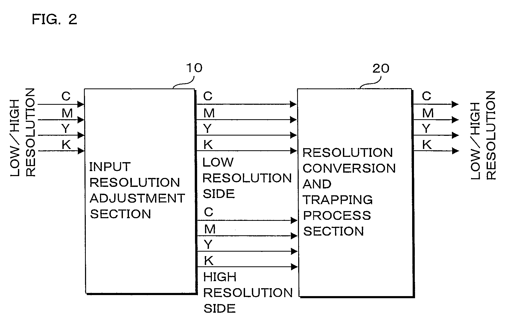
[0019]In other words, high-resolution input image data is converted to low-resolution image data, it is judged whether or not the trapping process is performed with respect to the low-resolution image data (hereinafter referred to as a trap judgment), and the trap color and a trap area are calculated using the low-resolution image data. Then, the trapping process is performed using the original high-resolution image data. This allows control of an increase in the circuit scale resulting from an increase in a memory required when the trap judgment and the like are performed using the high-resolution image data. In addition, since only the trap judgment is performed using the low-resolution image data, it is also possible to reduce the occurrence of problems such as the absence of information on output image data and the image quality degradation of the output image data resulting from the downsampling of the input image data.
[0021]Thus, when the input image data is low-resolution image data, the trap judgment is performed in the sate where the input image data is still low-resolution image data, and the trap color and the trap area are calculated. Subsequently, the trapping process is performed with respect to the image data obtained by converting the resolution of the input image data to the high resolution. This allows the control of the increase in the circuit scale.
[0022]In the present invention, an interpolation pixel is generated for low-resolution input image data, and a color difference between the generated interpolation pixel and a pixel of the input image data closest to the interpolation pixel is calculated. Then, when the calculated color difference is less than a predetermined value, a pixel value of the interpolation pixel is changed to the pixel value of the pixel of the input image data. When the calculated color difference is not less than the predetermined value, the pixel value of the interpolation pixel is changed to the pixel value of the pixel of the input image data at a predetermined position relative to the interpolation pixel. With this process, it is possible to increase the resolution of the low-resolution input image data to high resolution by reducing image blurring and a jaggy of the low-resolution input image data.
[0023]According to the present invention, high-resolution input image data is converted to low-resolution image data, it is judged whether or not the trapping process is performed with respect to the low-resolution image data (hereinafter referred to as the trap judgment), and the trap color and the trap area are calculated using the low-resolution image data. Subsequently, the trapping process is performed using the original high-resolution image data. This allows the control of the increase in the circuit scale resulting from the increase in the memory required when the trap judgment and the like are performed using the high-resolution image data. Further, since only the trap judgment is performed using the low-resolution image data, it is possible to reduce the occurrence of problems such as the absence of information on the output image data and the image quality degradation of the output image data resulting from the downsampling of the input image data.

Problems solved by technology

As a result, since the image forming apparatus needs a memory for storing the image data which is converted to the high-resolution image data, the problem occurs that a circuit scale is increased.
However, in the structure described in Japanese Patent Application Laid Open No. 2004-223850, since the trapping process is performed based on the bitmap data after the resolution thereof is converted, when the input image data has high resolution, a buffer for the high-resolution data is required so that it is not possible to reliably prevent the increase in the circuit scale.
However, in this case, high-resolution information is absent, which leads to the degradation of image quality.

Method used


Image

  • Image processing apparatus, image forming apparatus, image processing method and recording medium
  • Image processing apparatus, image forming apparatus, image processing method and recording medium
  • Image processing apparatus, image forming apparatus, image processing method and recording medium

Examples


Embodiment Construction

[0053]A description will be given hereinbelow of a preferred embodiment of an image processing apparatus according to the present invention with reference to the drawings.

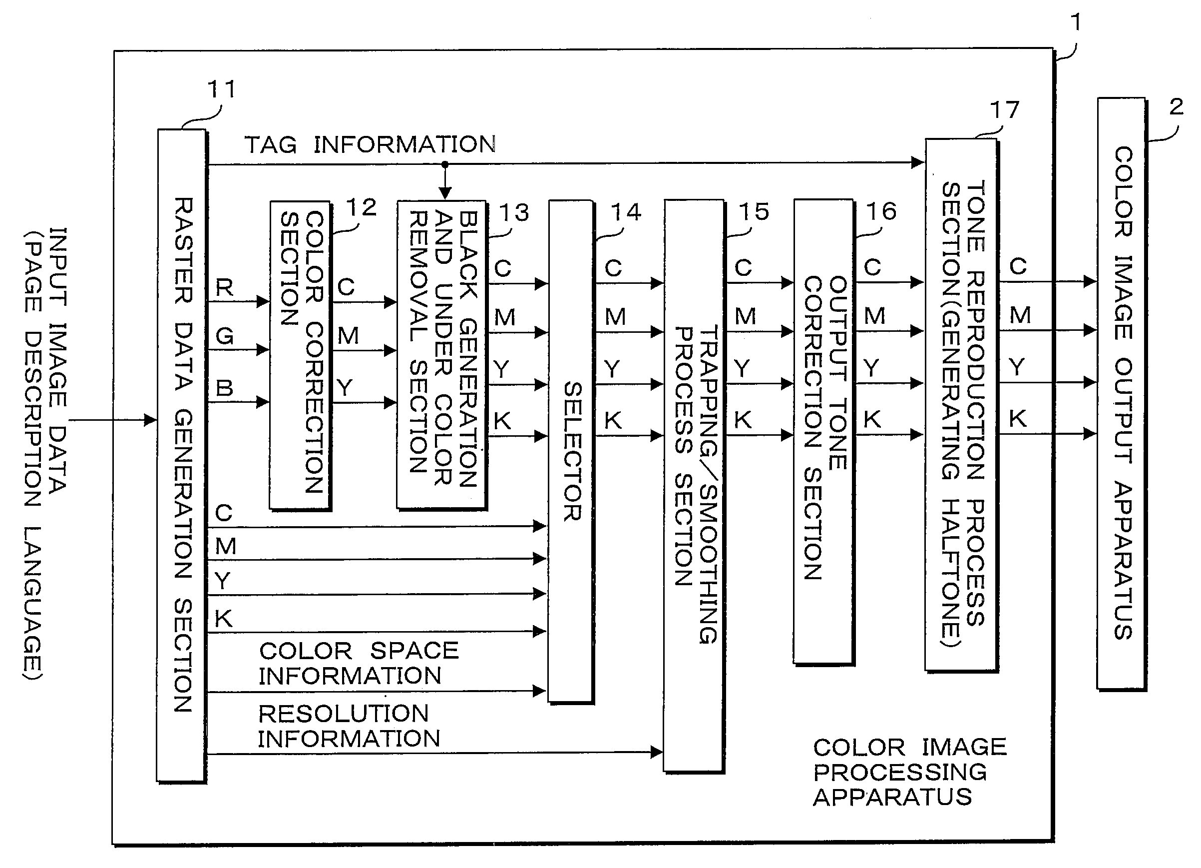
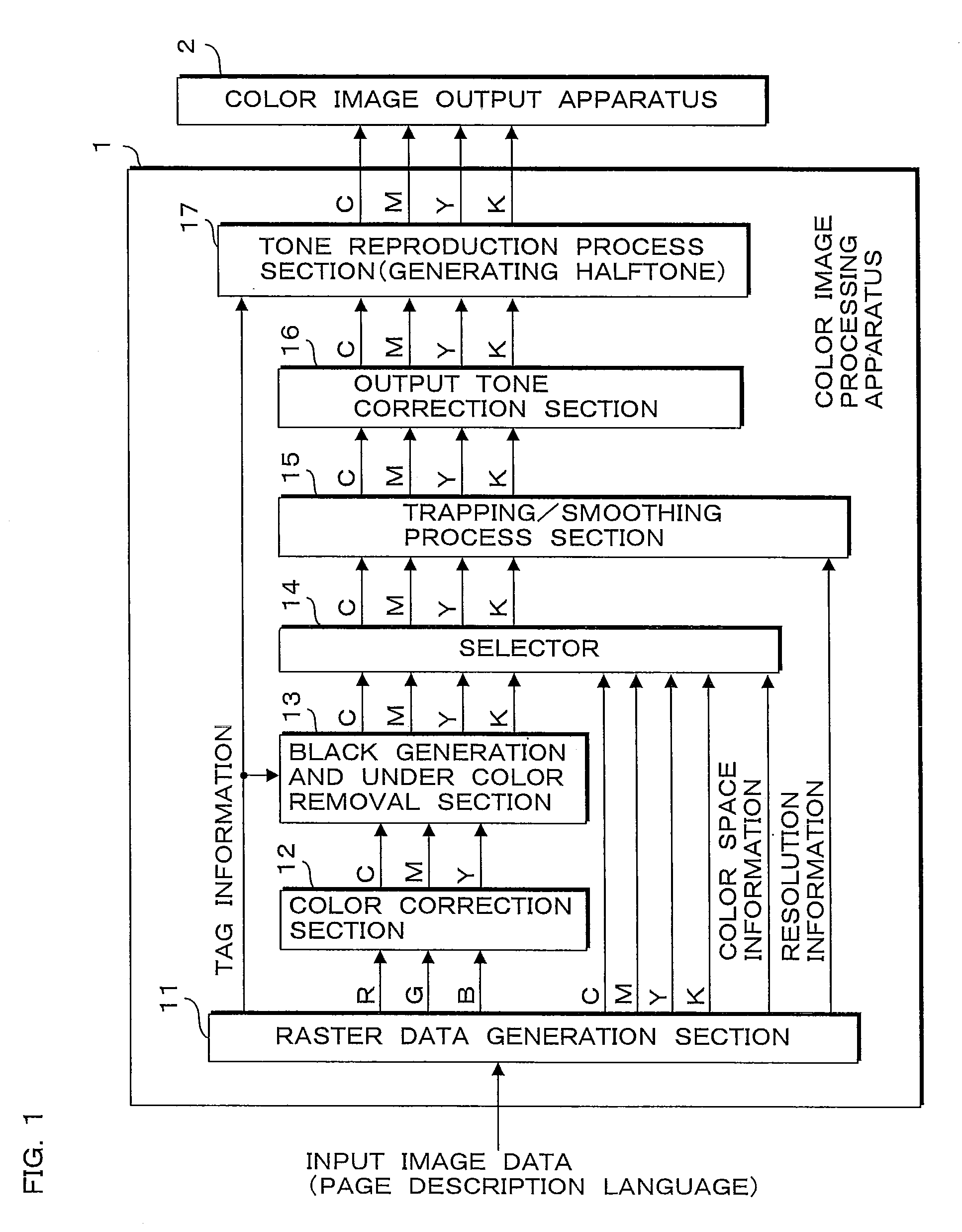
[0054]FIG. 1 is a block diagram illustrating a structure of a color image forming apparatus including the image processing apparatus according to the present invention. The color image forming apparatus according to the present embodiment performs image processing with respect to inputted image data (hereinafter referred to as input image data), and forms a color image on a sheet such as recording paper or the like based on the image data after the processing. The input image data is produced by using application software such as image editing software on a computer that is not shown. Subsequently, the input image data is converted to a page description language by a printer driver, and is transmitted to the color image forming apparatus from the computer via a network or the like.

[0055]As illustrated in FIG. 1, th...


PUM


Abstract

When input image data is high-resolution data, the input image data is downsampled to low-resolution data. Subsequently, it is judged whether or not the trapping process is performed with respect to an edge extracted based on the image data after the downsampling. When the trapping process is performed, a trap color is determined. Pixel data based on the determined trap color is upsampled based on the resolution of the input image data. Then, the trapping process is performed based on the input image data and the pixel data after the upsampling.

Description

CROSS-REFERENCE TO RELATED APPLICATIONS[0001]This Nonprovisional application claims priority under 35 U.S.C.§119(a) on Patent Application No. 2009-95181 filed in Japan on Apr. 9, 2009, the entire contents of which are hereby incorporated by reference.BACKGROUND[0002]1. Technical Field[0003]The present invention relates to an image processing apparatus, an image forming apparatus, an image processing method, and a recording medium recording a computer program for performing a process for superimposing pixel data of a plurality of color components.[0004]2. Description of Related Art[0005]In order to prevent degradation of image quality of an image formed on a paper medium by an image forming apparatus such as a copier or a printer, a trapping process and a smoothing process are proposed. A process for superimposing pixel data of a plurality of color components on each other (hereinafter referred to as a trapping process) is a process for preventing white gaps from appearing when a mis...

Claims


Application Information

Patent Timeline
IPC IPC(8): G06K15/02G06K9/00
CPCH04N1/58H04N1/40068
Inventor SAKAMOTO, AKIRA
Owner SHARP KK
Learn More