Cooling device utilizing internal synthetic jets

Inactive Publication Date: 2010-10-14
SIGNIFY HLDG BV
View PDF17 Cites 16 Cited by
  • Summary
  • Abstract
  • Description
  • Claims
  • Application Information

AI Technical Summary

Benefits of technology

[0005]In view of the above, an object of the invention is to solve or at least reduce the problems discussed above. In particular, an object is to provide a synthetic jet cooling device for cooling of electronic devices that requires virtually no extra space and weight, at a low additional cost.
[0007]The arrangement enables efficient cooling of an object through vortex shedding and synthetic jet impingement. By utilizing synthetic jets, cooling can be achieved also in essentially stagnating enclosures. Another advantage is that the object to be cooled is contained in the enclosure, why the cooling device typically requires virtually no extra space and weight, and can be provided at a low cost. In particular, this often permits multifunctional use of an existing enclosure, containing the object to be cooled, both for its original purpose (e.g. a reflector in a lamp, or a LED backlight module) and as an enclosure generating internal synthetic jets. Another advantage is that synthetic jets are less obtrusive, as they require only an aperture with diameter 1 / 10 of the distance between aperture and the cooled object. Thus, for applications in a reflector there is less optical perturbation, due to a small aperture diameter.

Problems solved by technology

An example of this is UHP (Ultra High Performance) lamps and LED (Light Emitting Diode) lamps, where the performance and lifetime is often limited by the heat developed.
However, disadvantages associated with prior art are noise, fouling, additional cost, limited lifetime, power dissipation, as well as extra space and weight.
As lighting applications are particularly demanding on all these issues (compared to e.g. microprocessors in computers), lighting customers and suppliers are reluctant to accept / introduce active cooling by forced convection.

Method used


Image

  • Cooling device utilizing internal synthetic jets
  • Cooling device utilizing internal synthetic jets
  • Cooling device utilizing internal synthetic jets

Examples


Embodiment Construction

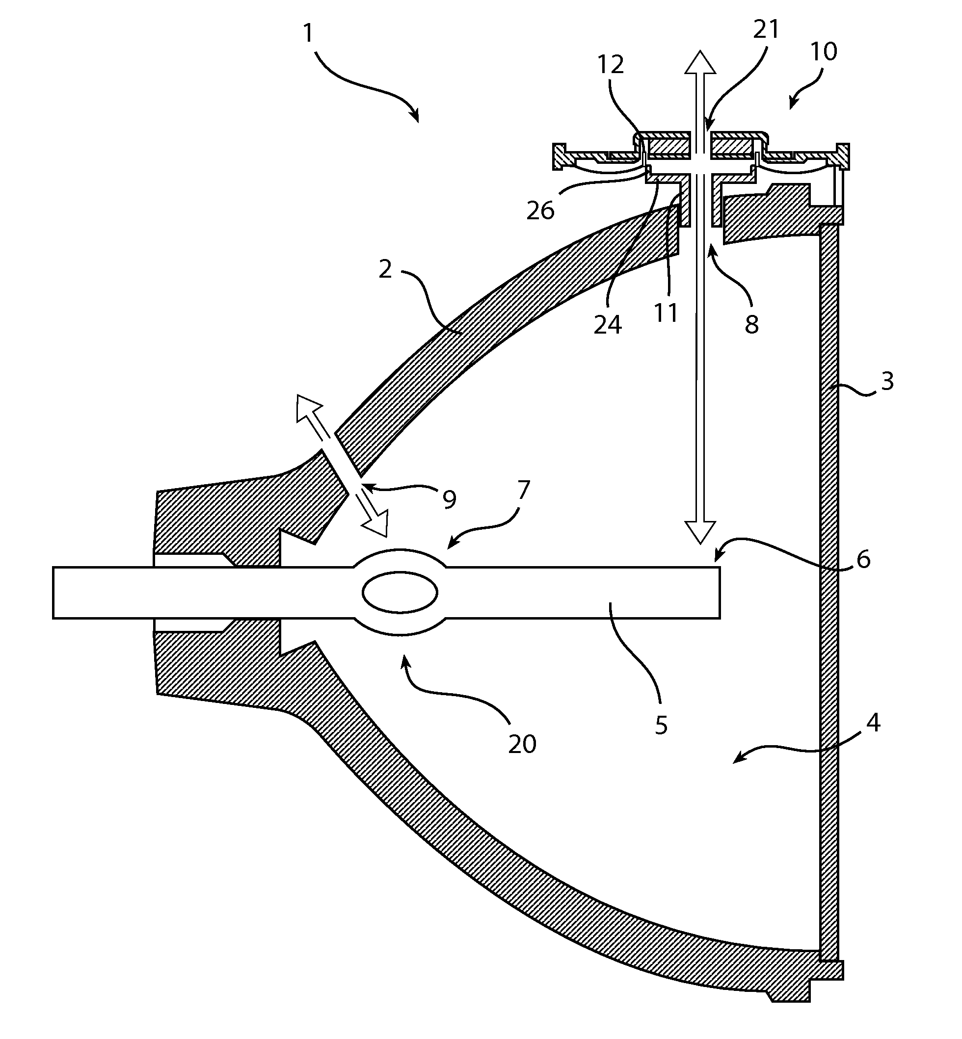
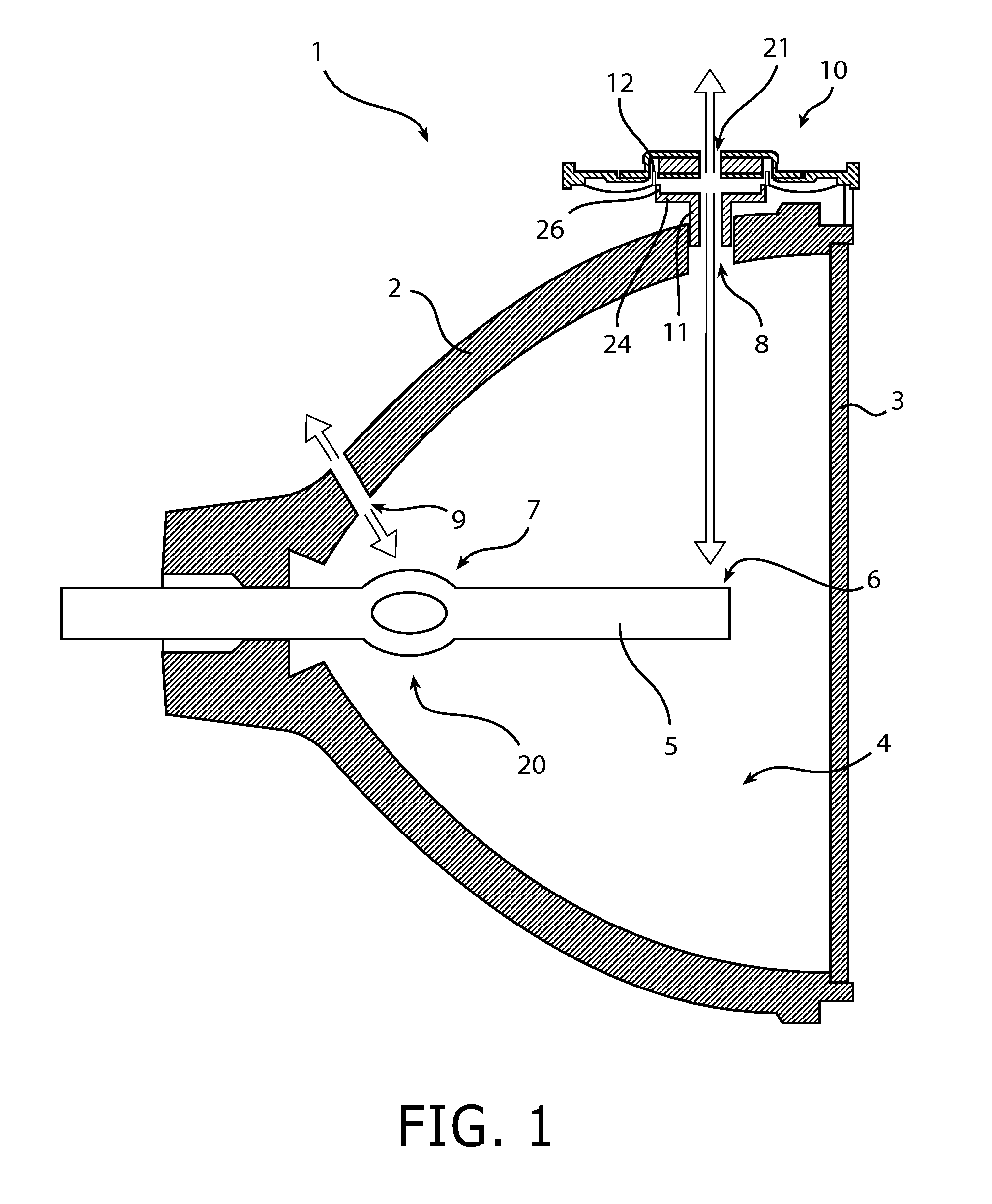
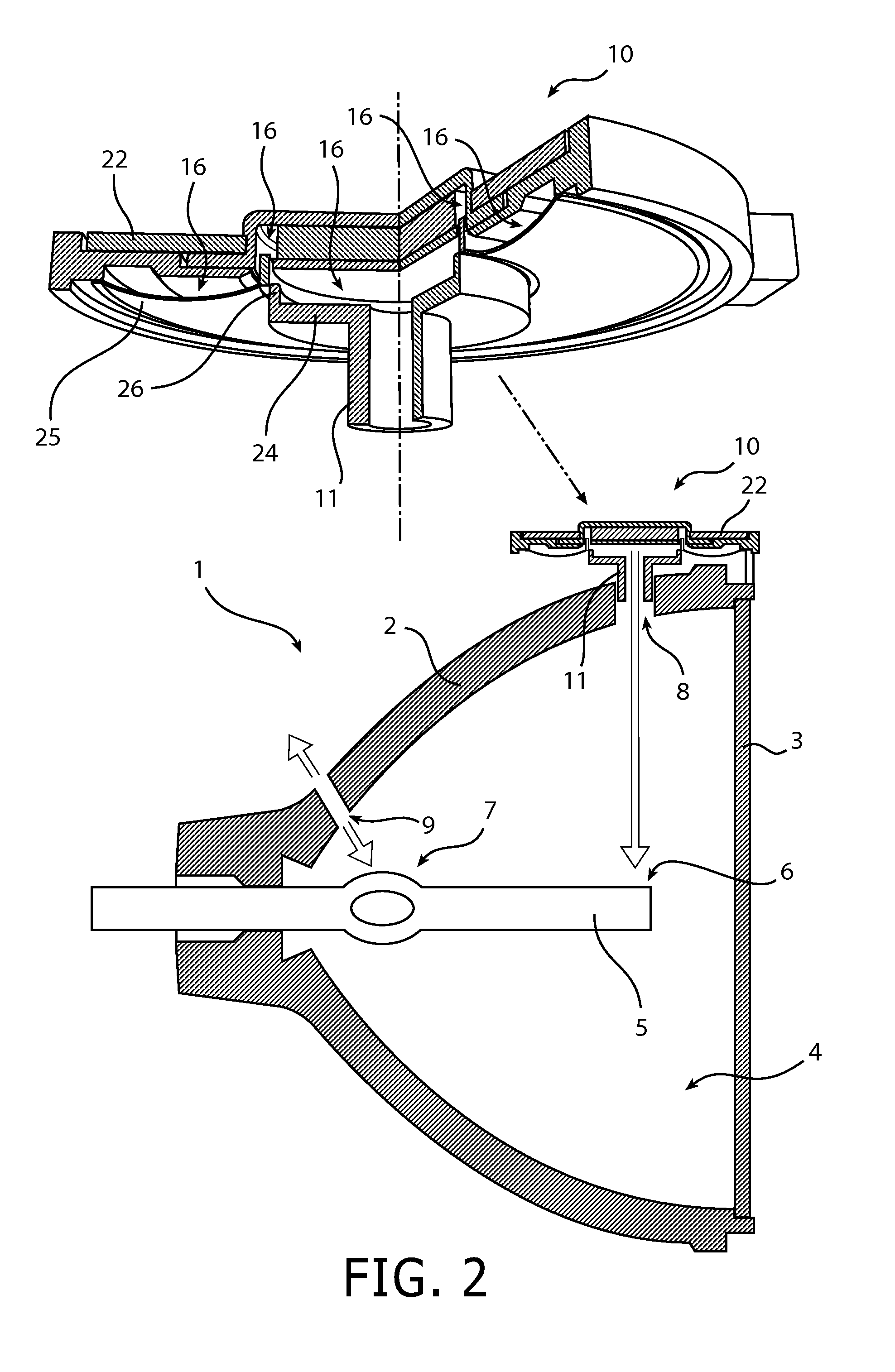
[0034]FIG. 1 illustrates an embodiment of the present invention for cooling of an Ultra High Performance (UHP) lamp 1. The UHP lamp 1 comprises a paraboloid reflector 2, and a front glass 3 airtight attached to the reflector 2 thereby forming an enclosure 4. The reflector 2 is here made of glass and has a reflective interior surface. A quartz burner 5 can be arranged inside the UHP lamp 1. For a typical UHP lamp 1, there is a first hot spot 6 located at the front pinch of the quartz burner (i.e. the end of the quartz burner closest to the front glass), and a second hot spot 7 located in the middle of the quartz burner (i.e. halfway between the ends of the quartz burner). Note that, provided that the quartz burner is horizontally arranged, the heat distribution at the middle of the quartz burner is such that the second hot spot 7 is located in the upper part thereof, whereas a cold spot 20 will form in the lower part thereof.

[0035]To prevent immanent crystallization these hot spots 6...


PUM


Abstract

A synthetic jet cooling device (1) for cooling an object (5), comprising: a transducer (10) adapted to generate velocity waves, and an enclosure (4) arranged to receive the velocity waves via an actuated aperture (8). The enclosure (4) is sufficiently large to generate, at the actuated aperture (8), an internal synthetic jet inside the enclosure (4). Furthermore, the enclosure (4) is arranged to contain the object (5), thereby enabling cooling of the object (5) by the internal synthetic jet. The arrangement typically permits multifunctional use of an existing enclosure, containing the object to be cooled, both for its original purpose (e.g. a reflector in a lamp, or a LED backlight module) and as an enclosure generating internal synthetic jets, why the cooling device typically requires virtually no extra space and weight, and can be provided at a low cost.

Description

TECHNICAL FIELD[0001]The present invention relates to a cooling device utilizing synthetic jets. The present invention further relates to an electronic device comprising such a cooling device.BACKGROUND OF THE INVENTION[0002]The need for cooling has increased in various applications due to higher heat flux densities resulting from newly developed electronic devices, being, for example, more compact and / or higher power than traditional devices. An example of this is UHP (Ultra High Performance) lamps and LED (Light Emitting Diode) lamps, where the performance and lifetime is often limited by the heat developed.[0003]In addition to natural convection, fans, either traditional propellers or synthetic jet coolers, can be utilized to enhance the heat transfer by forced convection. A typical synthetic jet actuator is disclosed in U.S. Pat. No. 6,123,145, comprising a housing having a flexible controllable diaphragm. As the diaphragm moves the volume in the chamber changes and vortices are...

Claims


Application Information

Patent Timeline
IPC IPC(8): F28D21/00
CPCF04F7/00F21V33/0056F21Y2101/02F21V29/63H01L2924/0002H01L2924/00F21Y2115/10
Inventor VAN DER TEMPEL, LEENDERTLAMMERS, JEROEN HERMANVAN OS, PETRUS JOHANNES MARIA
Owner SIGNIFY HLDG BV
Why Eureka
Try Eureka