Electromagnetically Shielded Subsea Power Cable

a technology of electromagnetic shielding and subsea power cables, applied in the direction of power cables, cables, insulated conductors, etc., can solve the problems of power consumption devices damaged, voltage waveforms for one or more phases,

Inactive Publication Date: 2010-10-07
OCEANEERING INTERNATIONAL
View PDF14 Cites 9 Cited by
  • Summary
  • Abstract
  • Description
  • Claims
  • Application Information

AI Technical Summary

Problems solved by technology

During the transmission of three phase alternating current (“AC”) through subsea power transmission cables, the different phases can interfere with each other, resulting in corrupted voltage waveforms for one or more of the phases.
This can result in voltage fluctuations which cause damage to power consumption devices connected to the receiving end of a subsea power transmission cable.

Method used


Image

  • Electromagnetically Shielded Subsea Power Cable
  • Electromagnetically Shielded Subsea Power Cable
  • Electromagnetically Shielded Subsea Power Cable

Examples


Embodiment Construction

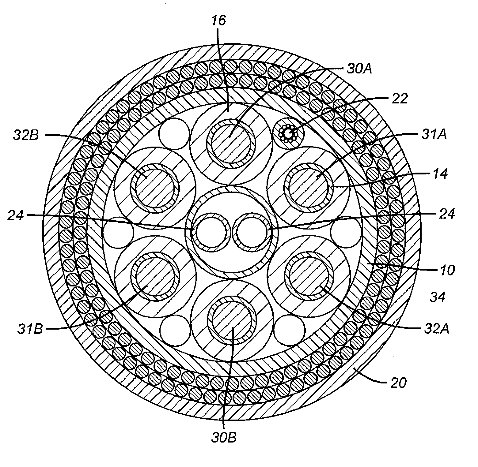
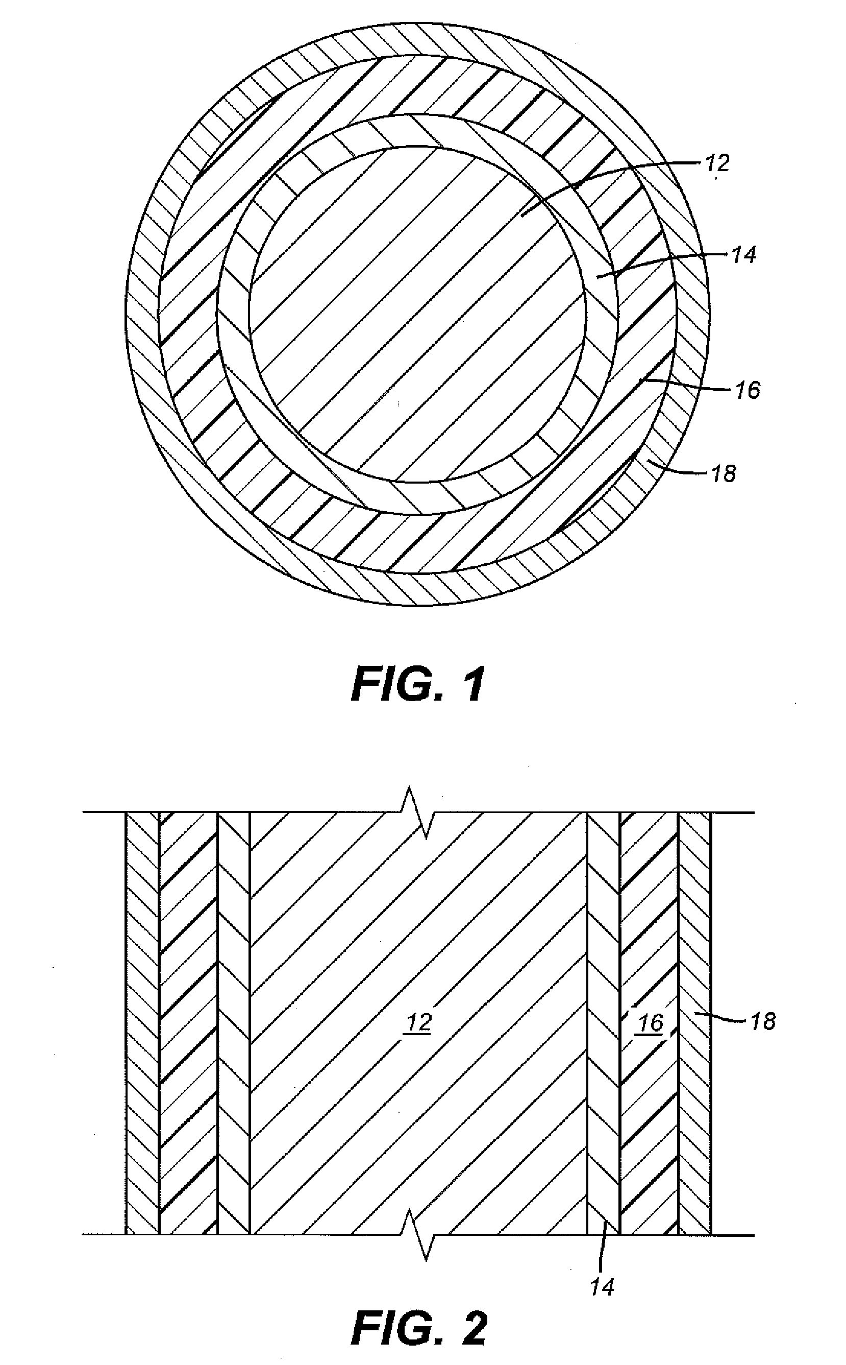
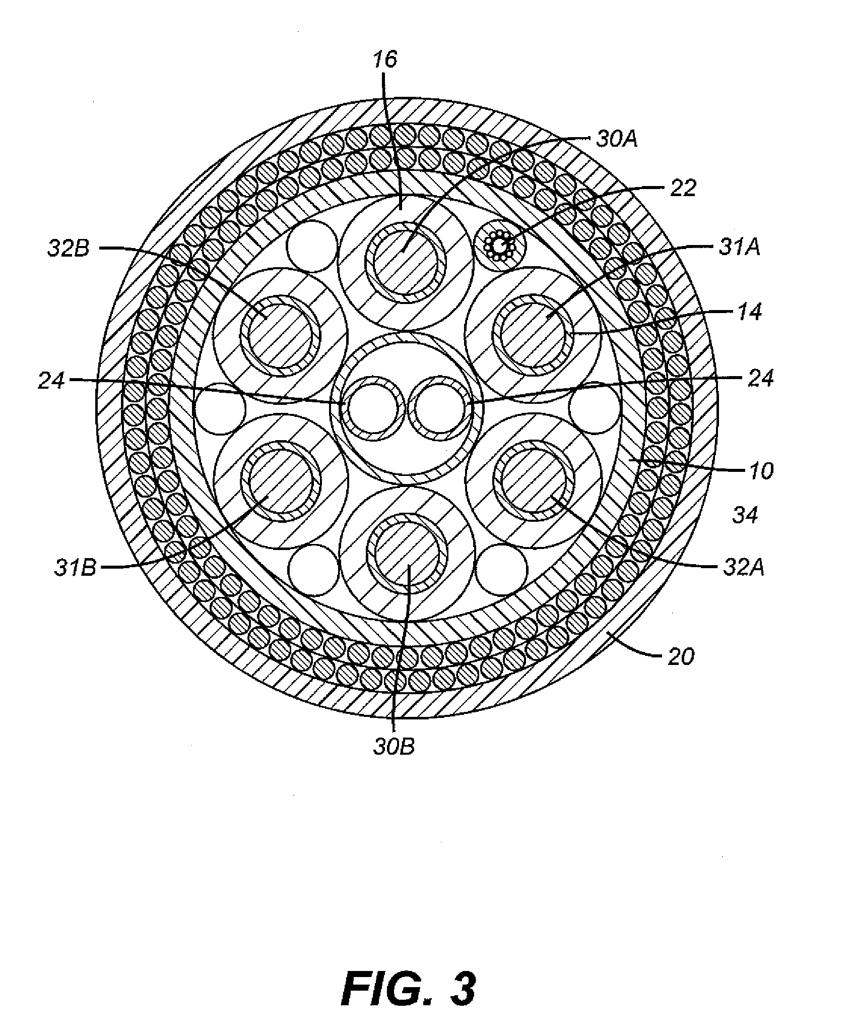
[0007]In a first preferred embodiment, the invention comprises an inner sheath 10 defining a inner region. In another preferred embodiment, the inner sheath is made from a thermoplastic material.

[0008]A first preferred embodiment of the invention further comprises at least one conductor 12 extending within the inner region. In a preferred embodiment, the conductor is made from a material that has a conductivity of at least 3.5×10⁷ siemens / meter. In another preferred embodiment, the conductor comprises copper. In another preferred embodiment, the conductor comprises aluminum. In another preferred embodiment, the conductor comprises direct current. In a single conductor embodiment, the invention is intended for use in seawater having sufficient conductivity to serve as a current return path.

[0009]A first preferred embodiment of the invention further comprises an electromagnetic shielding layer 14 directly contacting, and wrapped around, each conductor. In another preferred embodiment,...


PUM


Abstract

This invention is directed to an electromagnetically shielded subsea power cable containing at least one conductor, an electromagnetic shielding layer wrapped around each conductor, an insulation layer wrapped around each electromagnetic shielding layer, and a metallic shielding layer wrapped around each insulation layer. The subsea power cable can be used to transport power from a power source to a power user located subsea or at an intermediate facility, such as a platform.

Description

FIELD OF THE INVENTION[0001]This invention is directed to an electromagnetically shielded subsea power cable containing at least one conductor, an electromagnetic shielding layer wrapped around each conductor, an insulation layer wrapped around each electromagnetic shielding layer, and a metallic shielding layer wrapped around each insulation layer. The subsea power cable can be used to transport power from a power source to a power consumption device located subsea or at an intermediate facility, such as a platform.BACKGROUND OF THE INVENTION[0002]During the transmission of three phase alternating current (“AC”) through subsea power transmission cables, the different phases can interfere with each other, resulting in corrupted voltage waveforms for one or more of the phases. This can result in voltage fluctuations which cause damage to power consumption devices connected to the receiving end of a subsea power transmission cable. Such machines may include subsea pumps.[0003]One or m...

Claims


Application Information

Patent Timeline
IPC IPC(8): H05K9/00H01B7/17
CPCH01B9/023H01B7/14
Inventor WORMAN, PETER J.ABIB, LUCIANABALENA, ROSIANITADERRICKSON, SEAN
Owner OCEANEERING INTERNATIONAL
Why Eureka
Try Eureka