Fuel cell system

Inactive Publication Date: 2010-09-30
TOTO LTD
View PDF1 Cites 3 Cited by
  • Summary
  • Abstract
  • Description
  • Claims
  • Application Information

AI Technical Summary

Benefits of technology

[0014]The present invention has been devised in view of such problems and it is an object of the present invention to provide a fuel cell system including an SOFC that can accurately supply a small amount of water at a stage of shift to steam reforming and smoothly shift from partial oxidation reforming to steam reforming.

Problems solved by technology

Therefore, even if the water supply ability of the pump is increased for the predetermined time, excessive water is not supplied to the reformer.

Method used


Image

  • Fuel cell system
  • Fuel cell system
  • Fuel cell system

Examples


Embodiment Construction

[0036]An embodiment of the present invention is explained below with reference to the accompanying drawings. To facilitate understanding of the explanation, in the drawings, same reference numerals and signs are affixed to same components as much as possible and redundant explanation is omitted.

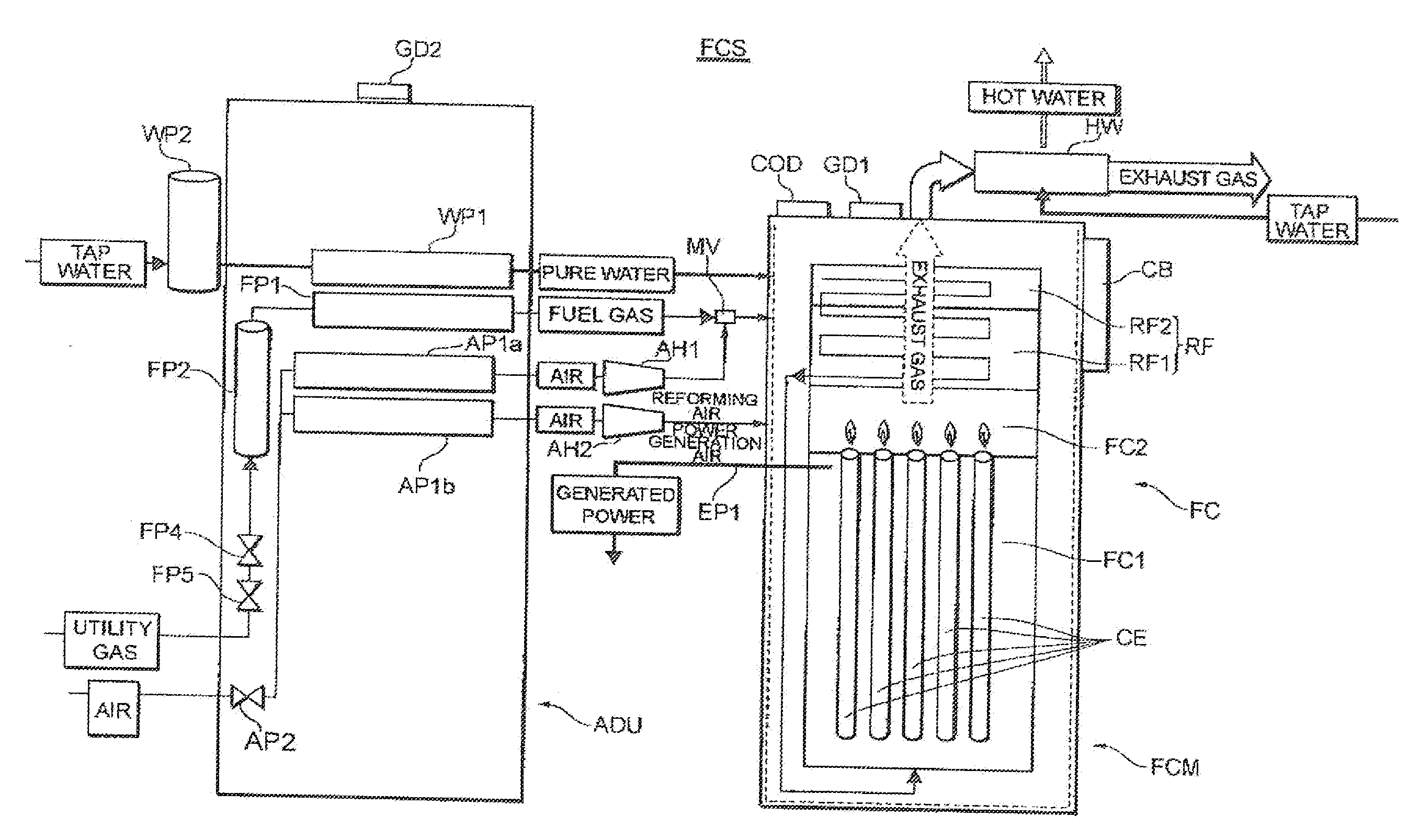
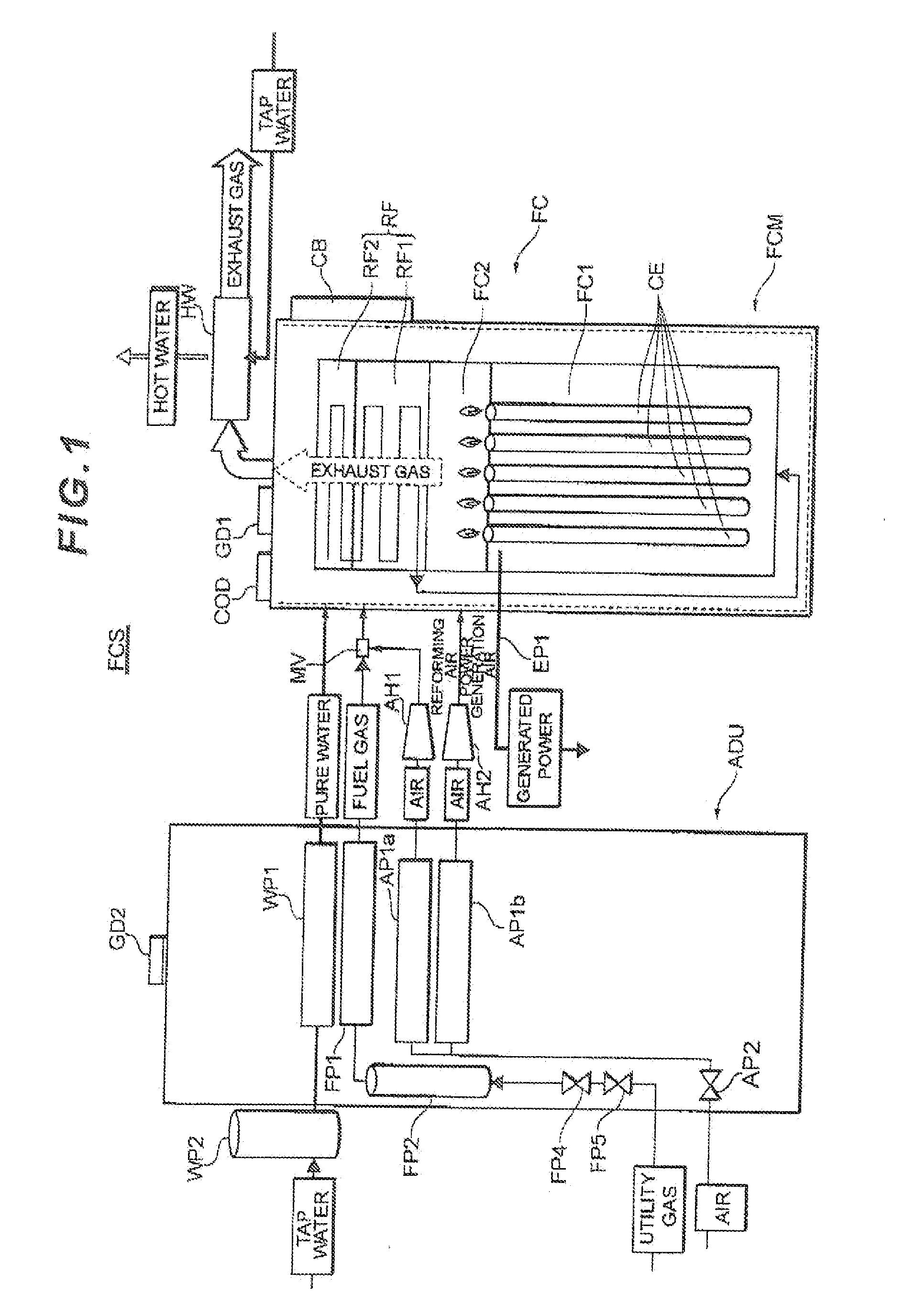
[0037]A fuel cell system according to an embodiment of the present invention is explained with reference to FIG. 1. FIG. 1 is a schematic diagram showing the overall configuration of a fuel cell system FCS according to this embodiment. As shown in cFIG. 1, the fuel cell system FCS includes a fuel cell'module FCM, an auxiliary device unit ADU, a water storage tank WP2, and a hot water producing device HW.

[0038]First, the fuel cell module FCM is explained. The fuel cell module FCM includes a fuel cell FC, a reformer RF, a control box CB, a carbon monoxide detector COD, and a combustible gas detector GD1. The fuel cell FC is a solid-oxide fuel cell and includes a power generation chamber FC1 and...


PUM


Abstract

The fuel cell system shifts, at least during start, in switching a pulse pump from a stop state to a pumping state to start pumping of the water, to normal control after performing start-operation-control for setting a water supply ability of the pulse pump higher for a predetermined time than the water supply ability during normal control.

Description

CROSS-REFERENCE TO RELATED APPLICATION[0001]This application claims benefit under 35 U.S.C. sctn. 119(a) of Japanese Patent Application No. 2009-086596, filed on Mar. 31, 2009, in the Japan Patent Office, the entire contents of which are incorporated herein by reference.BACKGROUND OF THE INVENTION[0002]1. Field of the Invention[0003]The present invention relates to a fuel cell system including a solid-oxide fuel cell (SOFC).[0004]2. Description of the Related Art[0005]Conventionally, as such a fuel cell system, a fuel cell system explained below is known. A solid-oxide fuel cell is formed in a bottomless or bottomed cylindrical shape, a fuel gas containing hydrogen is let through the inner side or the outer side of the fuel cell and an oxidant gas (the air) is let through the other side to cause a power generation reaction. The fuel gas is obtained by reforming a fuel gas containing hydrocarbon such as a utility gas. The reforming is performed by a reformer. The reforming is so-call...

Claims


Application Information

Patent Timeline
IPC IPC(8): H01M8/18
CPCC01B3/382Y02E60/525C01B2203/0261C01B2203/066C01B2203/1064C01B2203/1258C01B2203/148C01B2203/1604C01B2203/1609C01B2203/1619H01M8/04022H01M8/04268H01M8/04373H01M8/04425H01M8/04776H01M8/04828H01M8/0618H01M8/1206H01M2008/1293Y02E60/521C01B2203/0244H01M8/1231Y02E60/50
Inventor OOE, TOSHIHARUNAKANO, KIYOTAKAKAWAMURA, YOSHIYUKITSUCHIYA, KATSUHISASHIGEZUMI, TSUKASA
Owner TOTO LTD
Why Eureka
Try Eureka