
Wireless communication terminal and wireless communication system

a wireless communication system and wireless communication technology, applied in the field of wireless communication terminals, can solve the problems of affecting communication quality, requiring a relative long time, and reducing the accuracy of information for connection candidate base stations in the wireless communication system, so as to improve the accuracy of information for connection candidate base stations, reduce the size, power consumption and the cost of equipmen

Active Publication Date: 2010-09-30
NAT INST OF INFORMATION & COMM TECH
View PDF6 Cites 25 Cited by
  • Summary
  • Abstract
  • Description
  • Claims
  • Application Information

AI Technical Summary

Benefits of technology

[0063]According to the invention, since a wireless communication terminal and a connection management server are separately provided, there is no need to provide a storage unit for storing simultaneous detection information in the wireless communication terminal or a calculation processing unit for calculating a simultaneous detection probability. Consequently the above advantageous effects are enabled while at the same time reducing the size, reducing the power consumption and reducing the cost of the equipment.
[0064]Since accumulated simultaneous detection information is shared between a plurality of wireless communication terminals, selection accuracy is improved with respect to connection candidates.
[0065]According to the invention, since a function of accumulating simultaneous detection information is not provided, there is no requirement to provide components for that purpose. Consequently the size, the power consumption and the cost of the equipment can be reduced. Furthermore a wireless communication designated terminal can be provided which enables use of information from the connection management server for connection candidate base stations.
[0066]According to the invention, a designated terminal is provided for accumulating simultaneous detection information thereby enabling the accumulation of a large amount of simultaneous detection information. Thus the accuracy of information for connection candidate base stations in the wireless communication system can be improved.

Problems solved by technology

When switching between heterogeneous types of wireless communication networks, even when using the same type of wireless network, naturally a relatively long period of time is required to scan the network of different channels and execute a connection.
However when a communication terminal moves between base stations, the scanning of the connection-destination network or connection processing may not be performed in a timely manner resulting in the problem that the connection is cut off or communication quality is adversely affected.
Furthermore when scanning all networks or channels enabling communication in a communication terminal, the battery residual charge is reduced by the consumption of a large amount of power thereby adversely affecting the speed of other process due to the scanning process.
Although this method prevents unnecessary scanning operations when the local terminal is in standstill, it cannot be adapted when the terminal is migrating and furthermore entails the problem that reception signal intensity must be constantly measured.

Method used


Image

  • Wireless communication terminal and wireless communication system
  • Wireless communication terminal and wireless communication system
  • Wireless communication terminal and wireless communication system

Examples


example 1

Configuration of Single Wireless Communication Terminal

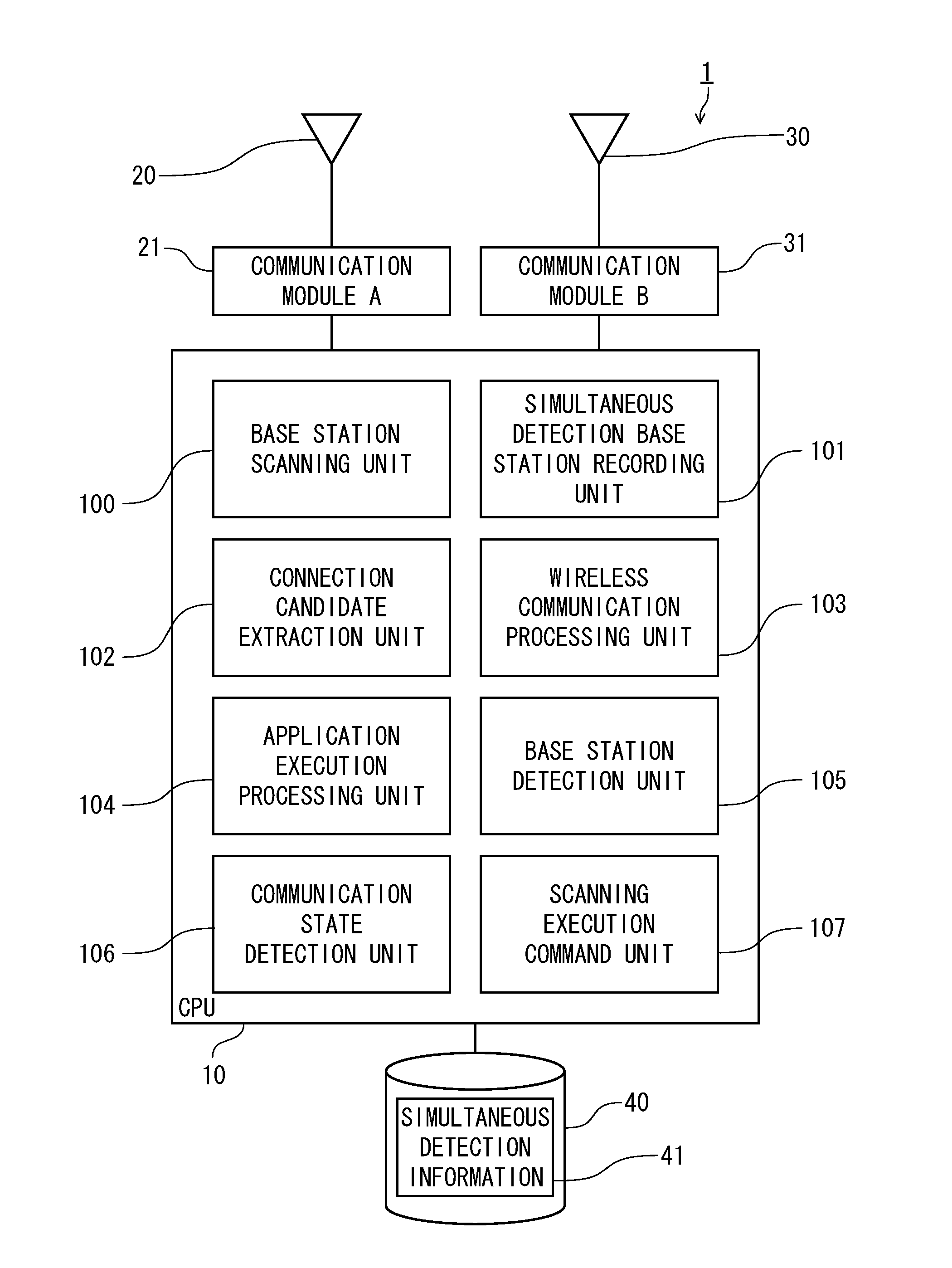
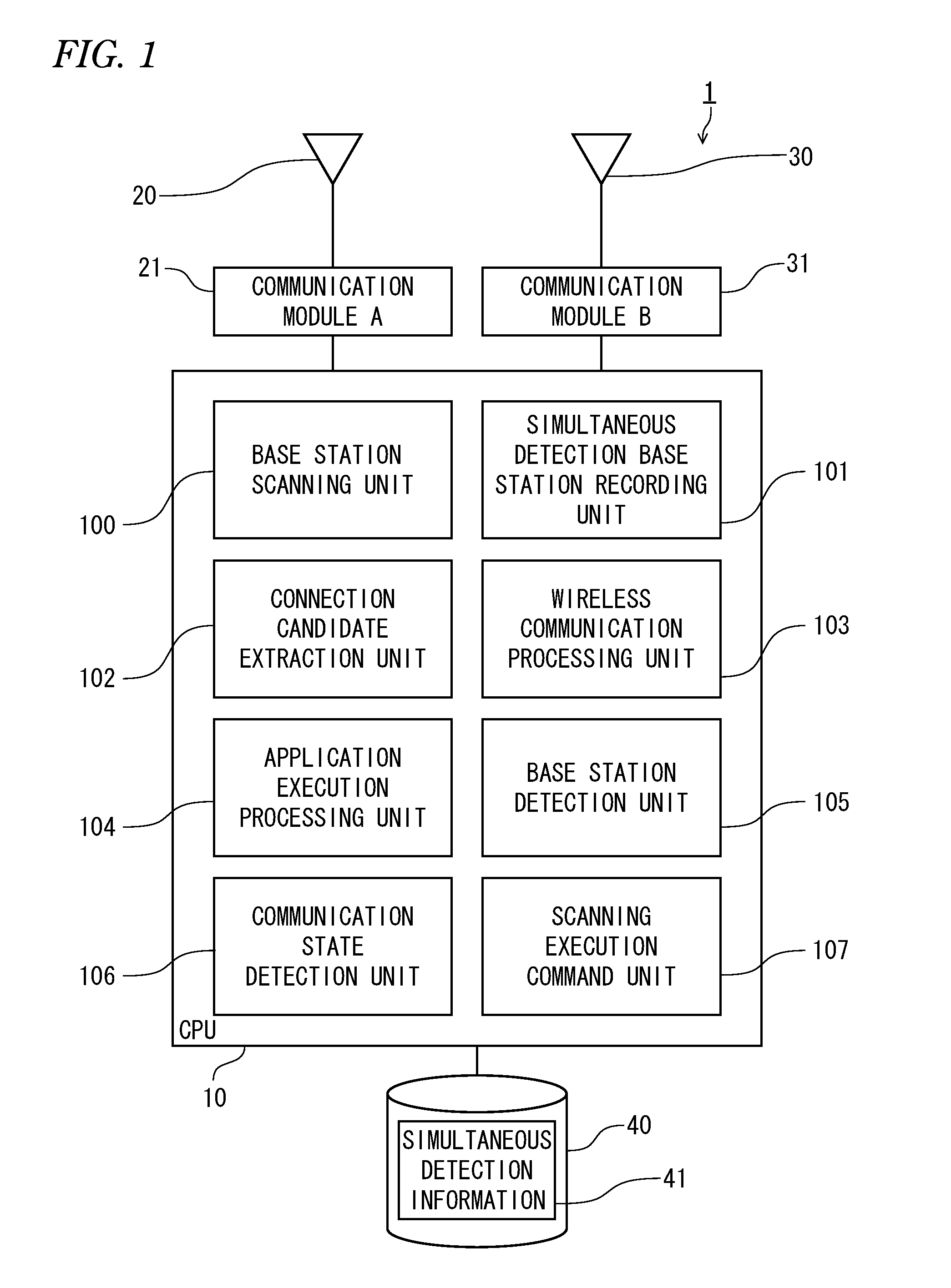
[0088]FIG. 1 shows a wireless communication terminal (1) according to the present invention. In addition to a known personal computer, the wireless communication terminal (1) may be realized by any of a mobile telephone terminal, or a mobile communication terminal such as a PDA.

[0089]As is well known, in addition to cooperation between a CPU (10) performing computational processing and the like and a memory (not shown), the configuration of this type of terminal is provided with a display device such as a monitor and an input device (not shown) such as a keyboard, mouse or touchpad. Furthermore an external storage device (40) configured by a hard drive or a flash memory, a communication module A(21) and an antenna (20) are provided for communication with a wireless communication network. A plurality of communication modules may be provided for communication with a plurality of wireless communication networks and, as shown in FIG...

example 2

Recording Three or More Simultaneous Detection Base Stations

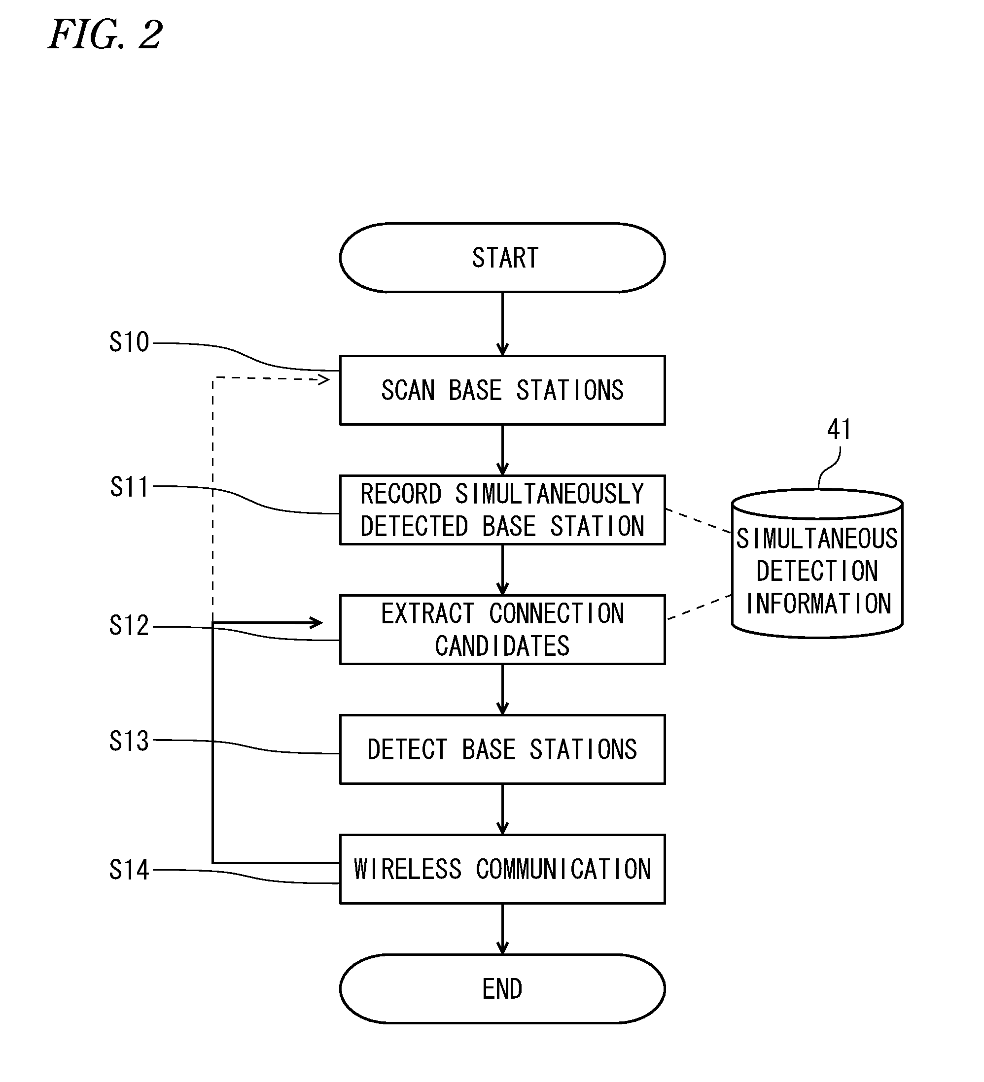
[0148]In the configuration in Example 1, when two base stations AP1, AP2 are simultaneously detected in the simultaneous detection base station recording unit (101), a value of 1 was added to the term for AP2 in the simultaneous detection information for AP1 and a value of 1 was added to the term for AP1 in the simultaneous detection information for AP2.

[0149]Even when three base stations AP1, AP2, AP4 are simultaneously detected, combinations of two base stations are created and a matrix (Expression 2) in which CDTA12, CDTA14, CDTA21, CDTA24, CDTA41, CDTA42 have respective values of 1 is created as described above.

[0150]According to this method, when the base station performing current communication is AP1, a simultaneous detection probability is calculated for any single base station when selecting the connection candidate base station for subsequent connection.

[0151]However as shown in FIG. 8, when a plurality of base st...

example 3

[0189]In Example 1 and 2, simultaneous detection information was described with reference to a process in which each element in CDTA was increased by a value of 1 based on the detection frequency for each base station. This example describes a process of varying an increasing value in response to a communication parameter related to a given base station and not only the use of a frequency.

[0190]In this example, a radio-wave intensity of a detected base station (radio field intensity) is used as a communication parameter to vary a value which is incremented in response to the intensity.

[0191]A radio-wave intensity is expressed in a range of 0-1 when a predetermined value which is sufficient for communication is given a value of 1 (100%). For example, when AP1 and AP2 are detected simultaneously, if the radio-wave intensity of AP2 is 0.8, a value of 0.8 is added to CDTA12. The frequency is counted with respect to DOA2 and incremented by a value of 1.

[0192]In wireless communication net...


PUM


Abstract

To reduce power consumption for scanning and maintain communication quality by reducing the time for scanning or connection when a wireless communication terminal switches between networks or base stations. A wireless communication terminal 1 enabling connection with a plurality of base stations disposed in different positions which includes a base station scanning unit 100 detecting and scanning a base station capable of communication at the current position of the wireless communication terminal, a simultaneous detection base station recording unit 101 recording simultaneously detected base stations as simultaneous detection information in a storage unit, a connection candidate extraction unit 102 and a first communication unit 103 performing communication by connection with the extracted connection candidate base station. Based on the simultaneous detection information, the connection candidate extraction unit 102 extracts a base station having the possibility of simultaneous detection with the currently connected base station as a connection candidate base station.

Description

TECHNICAL FIELD[0001]The present invention relates to a wireless communication terminal and a system for the same performing wireless communication by switching a connection-destination base station and, in particular, relates to a technique for facilitating and optimizing selection by a wireless communication terminal of the base station for connection after the currently connected base station.BACKGROUND ART[0002]Broad-based research is continuing into the creation of a network such as an internet and a ubiquitous network capable of communication at all times and from all places.[0003]The present applicant has carried out research into techniques of seamless handover between heterogeneous wireless networks (Non Patent Literature 1 and 2) and research into software wireless techniques enabling connection with heterogeneous wireless interfaces to switch the wireless systems (Non Patent Literature 3).[0004]Currently since mobile communication terminals such as personal digital assist...

Claims


Application Information

Patent Timeline
Patent Type & Authority Applications(United States)
IPC IPC(8): H04W4/00
CPCH04W48/20Y02B60/50H04W88/06Y02D30/70
Inventor ISHIZU, KENTAROMURAKAMI, HOMAREMIYAMOTO, GOHTRAN, HA NGUYENFILIN, STANISLAVHARADA, HIROSHI
Owner NAT INST OF INFORMATION & COMM TECH
Learn More