White light emitting diode, white light emitting apparatus, and linear illuminator using the same
a light emitting diode and light emitting device technology, applied in lighting and heating devices, process and machine control, instruments, etc., can solve the problems of insufficient selection of selectors, inability to adjust the range available for the adjustment of average current value and/or duty ratio, and the manufacture defect of white light emitting diodes. achieve the effect of improving the productivity, and reducing the cost of production
- Summary
- Abstract
- Description
- Claims
- Application Information
AI Technical Summary
Benefits of technology
Problems solved by technology
Method used
Image
Examples
first embodiment
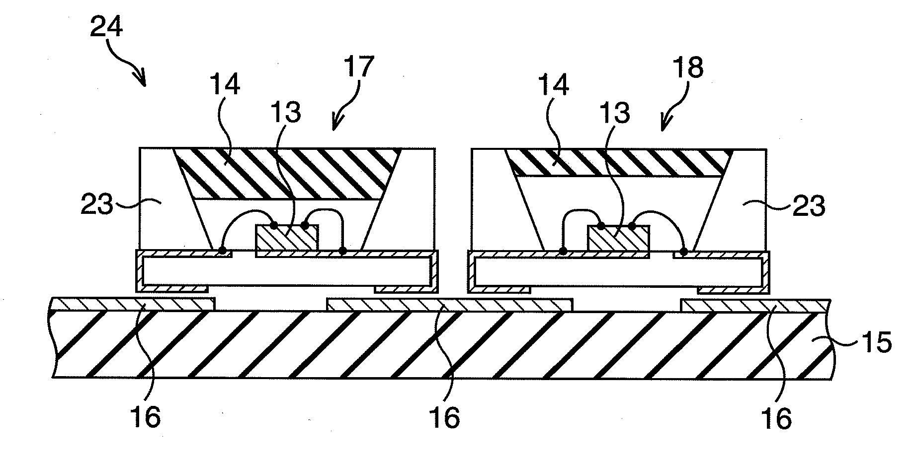
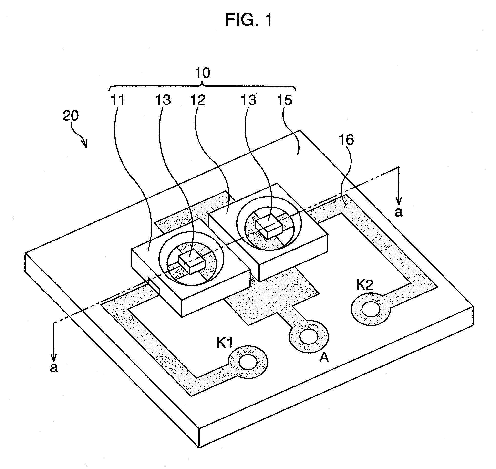
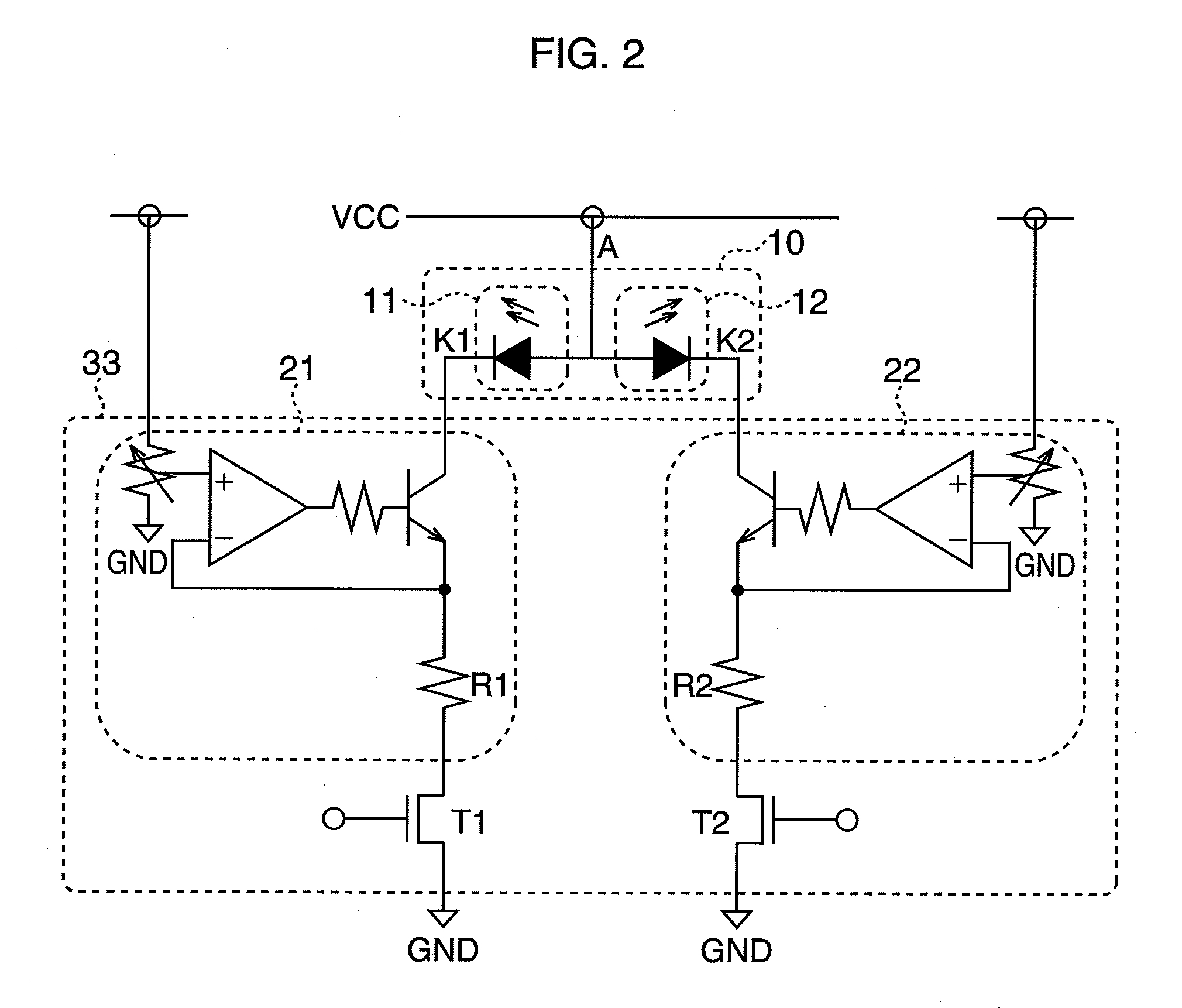
[0047]A white light emitting apparatus according to the first embodiment is provided with two or more white light emitting diodes. Each of the white light emitting diodes includes a blue LED chip, and a fluorescent layer which is excited by a radiation light emitted by the blue LED chip and emits a yellow light. Yellow is a complementary color of blue. In the first embodiment, a white light emitting apparatus 20 having the two or more white light emitting diodes will be explained below with reference to FIGS. 1 to 5.
[0048]FIG. 1 illustrates a light source section 10 of the white light emitting apparatus 20 of the first embodiment. In the white light emitting apparatus 20, a first white light emitting diode 11 and a second white light emitting diode 12 are adjacently mounted to a printed circuit board 15. The first white light emitting diode 11 emits a white light which is more yellowish and deviated from the white point on a chromaticity diagram. The second white light emitting diod...
second embodiment
[0065]A linear illuminator 50 according to a second embodiment uses the white light emitting apparatus 20 according to the first embodiment. The linear illuminator 50 will be explained in detail below with reference to FIGS. 6 to 8.
[0066]The linear illuminator 50 of the second embodiment is used to illuminate a surface of a manuscript such as a paper in an image reading apparatus, for example. The linear illuminator 50 is, as illustrated in FIG. 6, provided with a bar-shaped light guide member 51 that is formed of a transparent material and has a light incident surface 54 at one end thereof, and the light source section 10 disposed toward the light incident surface 54. The light source section 10 is connected with the current control section 33 via terminal lead 62 as in the case of the first embodiment (not illustrated in FIG. 6). The light guide member 51 is provided with a light guiding section 52 guiding an incident light from the light incident surface 54 in the longitudinal di...
third embodiment
[0078]In a third embodiment, two blue LED chips are mounted to one package, and a YAG fluorescent layer covers each of the blue LED chips and has a thickness different from those of others. With reference to FIGS. 9A and 9B, a method for manufacturing a white light emitting diode 71 of the third embodiment will be explained below.
[0079]A package 72 is formed of a resin into a box shape with the top thereof being open, and the package 72 has wiring of a lead frame at the bottom thereof, so that an anode wiring 75 of a lead frame at the bottom has a first blue LED chip 73 and a second blue LED chip 74 disposed thereon. Then, the cathode terminal and the anode terminal thereof are connected to the cathode wiring 76 and the anode wiring 75 of the lead frame respectively by using a wire-bonding method for example, to be mounted (FIG. 9A). The top opening may have a dimension of about 2.5 mm or less in the longitudinal and lateral directions thereof, for example.
[0080]Next, a resin soluti...
PUM
 Abstract
Description
Claims
Application Information
 - R&D
- Intellectual Property
- Life Sciences
- Materials
- Tech Scout
- Unparalleled Data Quality
- Higher Quality Content
- 60% Fewer Hallucinations
Browse by: Latest US Patents, China's latest patents, Technical Efficacy Thesaurus, Application Domain, Technology Topic, Popular Technical Reports.
© 2025 PatSnap. All rights reserved.Legal|Privacy policy|Modern Slavery Act Transparency Statement|Sitemap|About US| Contact US: help@patsnap.com


