
Particle Stabilized Emulsions for Enhanced Hydrocarbon Recovery

a technology of hydrocarbon recovery and stabilized emulsions, which is applied in the direction of carbon-dioxide storage, chemistry apparatuses and processes, and well accessories. it can solve the problems of invariably contaminated water, more oil being recovered, and waste-related concerns

Inactive Publication Date: 2010-09-30
UNIV OF MASSACHUSETTS
View PDF1 Cites 119 Cited by
  • Summary
  • Abstract
  • Description
  • Claims
  • Application Information

AI Technical Summary

Benefits of technology

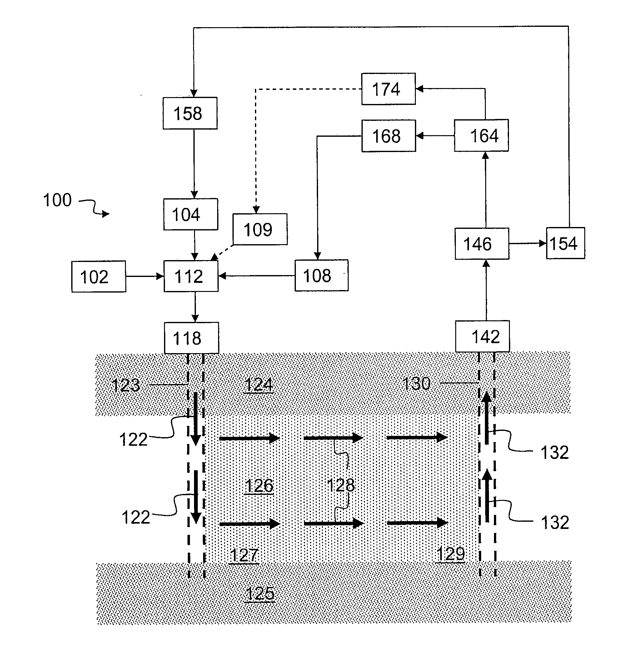
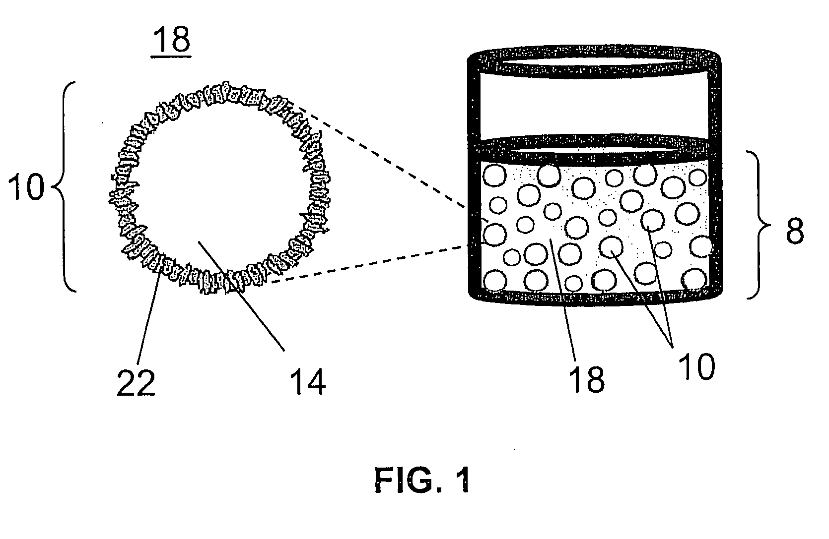
The present invention provides methods and systems for hydrocarbon recovery from subterranean formations. The invention addresses various shortcomings and deficiencies of previous methods, such as incomplete recovery of gas and oil, unstable emulsions, and waste management. The invention offers a tertiary method of subterranean oil recovery using a fluid medium comprising an emulsion of liquid carbon dioxide and / or supercritical carbon dioxide, an aqueous component, and a particulate component selected from hydrophilic and hydrophobic components. The invention also provides a method of using a particle-stabilized emulsion for tertiary oil recovery.

Problems solved by technology

Carbon dioxide flooding alone, or WAG injection, may not always result in more oil being recovered.
These and related issues are also encountered in the context of coal beds.
Even so, waste-related concerns often arise.
The produced water is invariably contaminated with toxic metals, salts and other contaminants that render it unsuitable for drinking, irrigation or cost-effective purification.
The lack of safe and permanent disposal methods for produced water further impedes coal bed methane production—not only in the US but world-wide.
As with tertiary methods for oil recovery, methane / gas extraction has used liquid / supercritical carbon dioxide flooding, but is adversely affected by much the same issues and concerns.

Method used


Image

  • Particle Stabilized Emulsions for Enhanced Hydrocarbon Recovery
  • Particle Stabilized Emulsions for Enhanced Hydrocarbon Recovery
  • Particle Stabilized Emulsions for Enhanced Hydrocarbon Recovery

Examples


example 1a

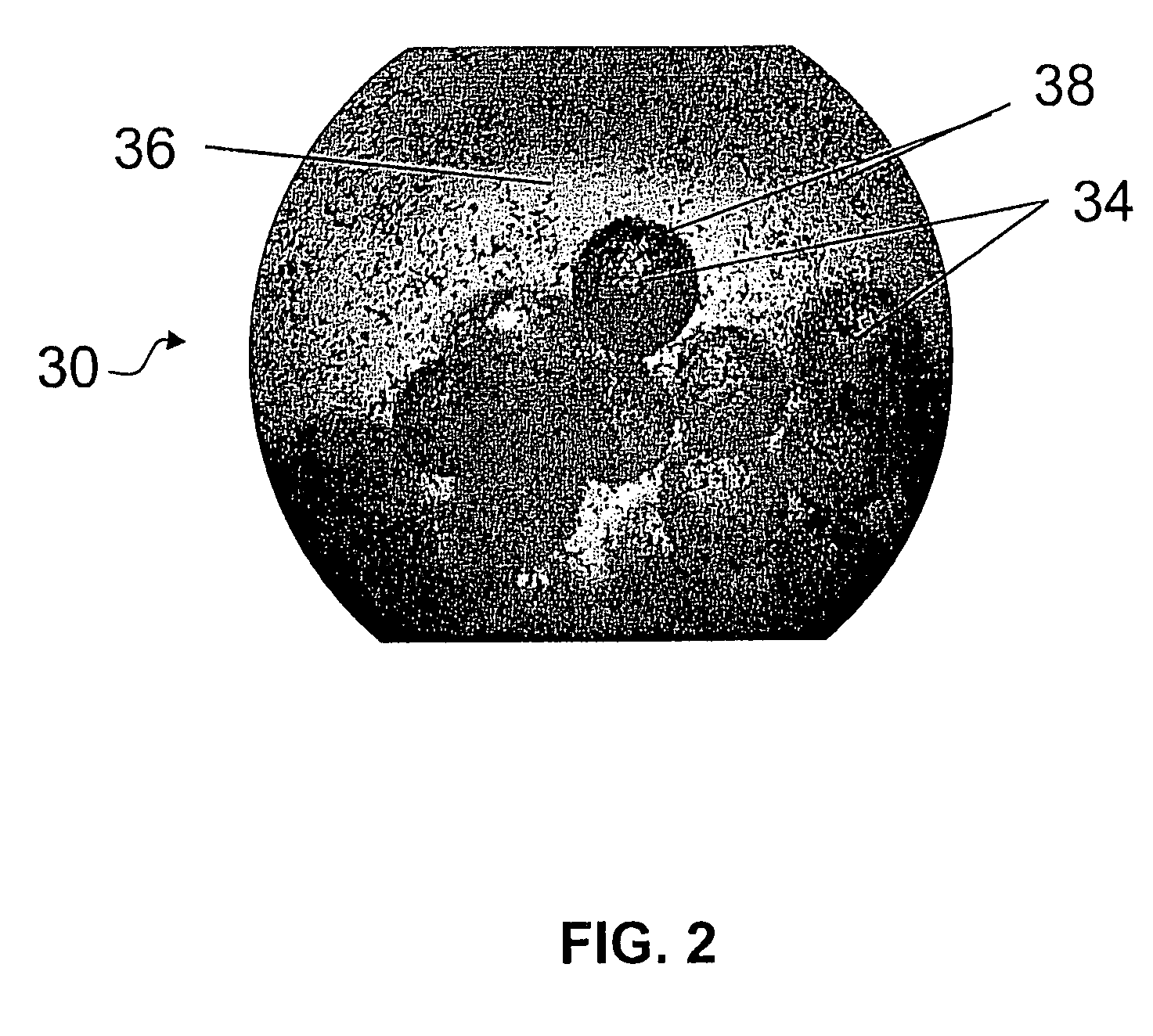
[0115]Particles-stabilized CO2-in-aqueous liquid (C / A) and aqueous liquid-in-CO2 (A / C) macroemulsions were formed in a high-pressure batch reactor (HPBR) with view windows using an apparatus similar to the one shown in FIG. 4. The reactor included a stainless steel pressure cell of 85 mL internal volume equipped with tempered glass windows (PresSure Products G03XC01B). The windows were placed 180° apart, with one illuminated with a 20 W, 12 V compact halogen bulb and the other allowing observation with a video camera. The view window diameter was 25 mm. The window diameter was used as a scale for determining droplet diameter sizes. The reactor was equipped with a pressure-relief valve (Swagelok R3− A), a thermocouple (Omega KMQSS-125G-6), a pressure gauge (Swagelok PGI-63B), a bleed valve (Swagelok SS-BVM2), and a 3.2 mm port for admitting CO2. A cylindrical magnetic stir bar with a cross shape on top (VWR Spinplus) was utilized for internal mixing. Unless otherwise indicated, the s...

example 1b

[0116]For preparation of C / A macroemulsions, the following procedure was carried out: a slurry of the hydrophilic particles in water was prepared, a measured volume of the slurry was added to the HPBR through an opening, the opening was closed, and a measured volume of liquid or supercritical CO2 was added by means of a syringe pump. Unless otherwise indicated, the proportions of the ingredients were as follows: 10 g of particulate matter suspended in 65 mL of water and ˜18-20 mL (balance) of liquid CO2. The pressure in the HPBR was 17.2 MPa and the temperature was 15° C.

example 1c

[0117]For preparation of A / C macroemulsions, the preceding procedure was reversed. First, the dry matter was added to the HPBR, followed by injection of liquid CO2. After agitation, a high-pressure syringe pump was used to inject water to a set pressure of 17.2 MPa. For the A / C emulsions, a proportion of ˜65 mL of CO2 / (20 mL of H2O) was used.


PUM


Abstract

Hydrophobic and hydrophilic particles as can be used to stabilize emulsions for hydrocarbon extraction and / or recovery.

Description

BACKGROUND OF THE INVENTION[0001]Hydrocarbon (e.g., crude oil, or simply oil) recovery may be classified as primary, secondary and tertiary recovery. In primary recovery, the crude oil is simply drawn out of a subterranean formation by a pumping action. The hydrostatic pressure resulting from the overlying strata drives the oil toward the pumped well. Primary recovery methods usually recover only 20-30% of the original oil in place (OIP) estimated to be in the formation. Secondary recovery refers to the injection of pressurized liquid water or water vapor (steam) into the formation via a bore pipe. The additional pressure of the injected water, and / or the heating action of the steam drives more of the crude oil toward the pumped well. In such a manner, an additional 10-20% of the original OIP estimated to be in the formation may be recovered. Tertiary recovery involves methods to reduce the viscosity and dissolve the oil and / or increase its mobility in some fashion. Injecting liquid...

Claims


Application Information

Patent Timeline
Patent Type & Authority Applications(United States)
IPC IPC(8): E21B43/16E21B43/22
CPCC09K8/58Y02C10/14E21B43/164E21B41/0064Y02P90/70Y02C20/40
Inventor GOLOMB, DAN S.RYAN, DAVIDBARRY, GENESWETT, PETERWOODS, MICHAEL
Owner UNIV OF MASSACHUSETTS
Learn More