Apparatus for inhibiting pressure fluctuations and moisture contamination within solar collectors and multi-glazed windows

a solar collector and multi-glazed technology, applied in the safety of solar heat collectors, lighting and heating apparatus, separation processes, etc., can solve the problems of moisture accumulation, solar heat collectors and double-glazed or multi-glazed windows are typically plagued, and the interior space heat cannot be easily carried out. , to achieve the effect of minimizing pressure changes within the chamber, minimizing stresses applied to the chamber seal, and prolonging the life of the chamber seal

Inactive Publication Date: 2010-09-30
SOUCY PAUL B
View PDF1 Cites 7 Cited by
  • Summary
  • Abstract
  • Description
  • Claims
  • Application Information

AI Technical Summary

Benefits of technology

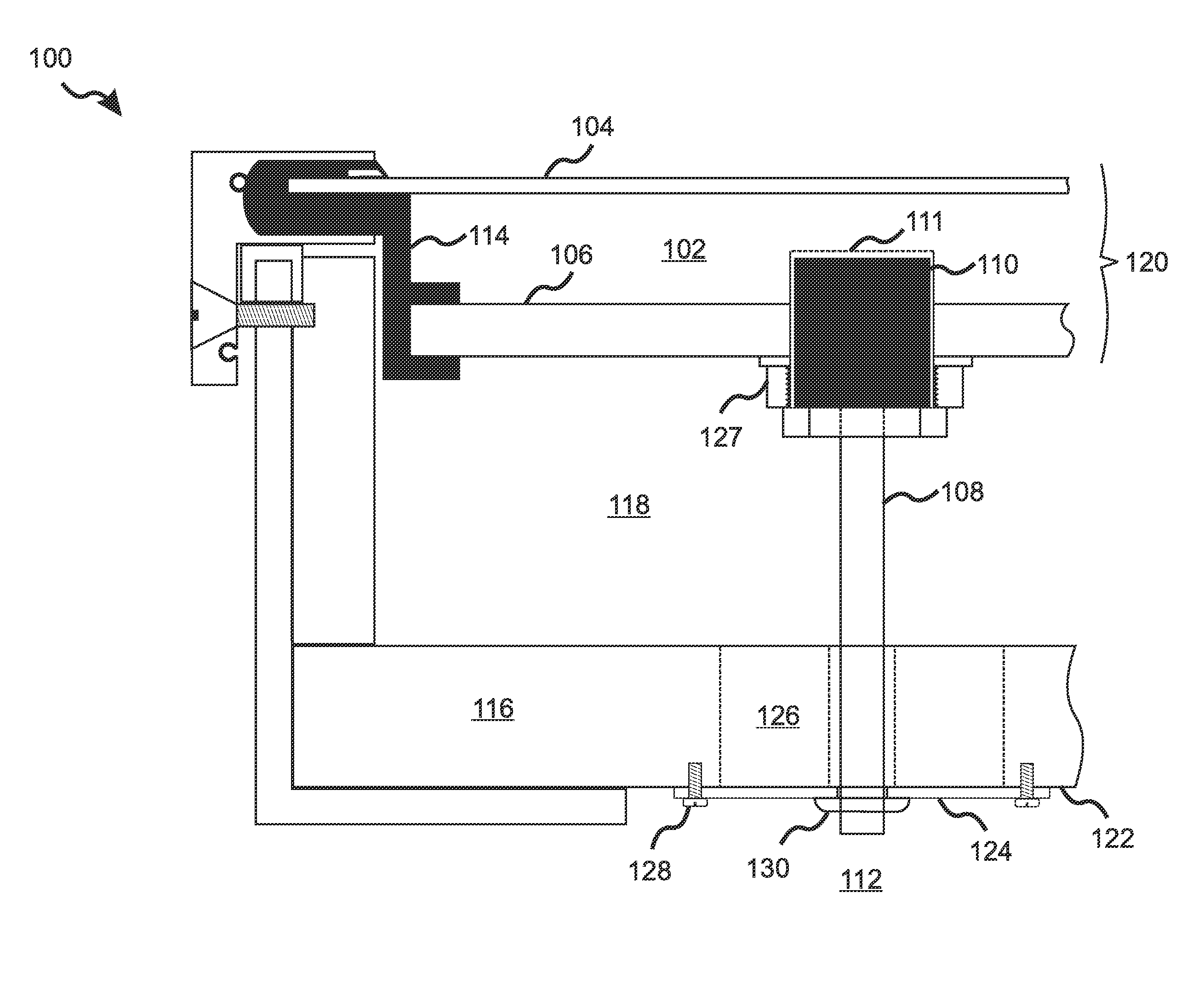
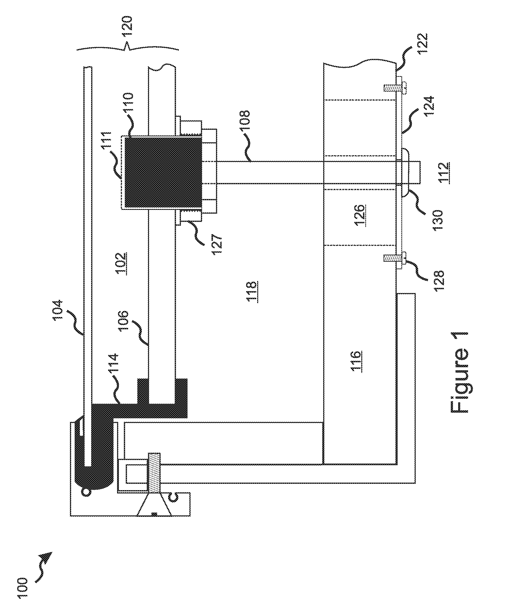
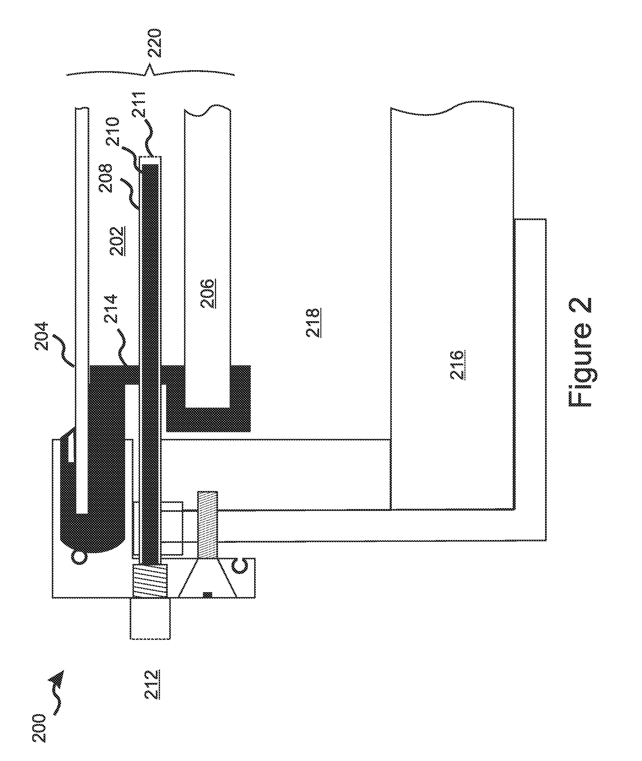
[0007]One aspect of the present invention is a solar collector or multi-glazed window comprising a sealed chamber of fixed volume formed between a light transmissive layer and an adjacent layer, the sealed chamber being filled with air or another gas, wherein a vent or breathing port is provided that enables gas communication through a desiccant plug between the interior of the chamber and an exterior gas or air environment. Changes in the air or gas temperature and pressure within the chamber cause gas to flow through the desiccant material, thereby minimizing pressure changes within the chamber and minimizing stresses applied to the chamber seals. This significantly extends the lives of the chamber seals while at the same time inhibiting entry of moisture into the chamber.
[0008]Another aspect of the present invention is a solar collector or multi-glazed window comprising a sealed chamber of expandable volume formed between a light transmissive layer and an adjacent layer. The chamber volume is able to expand and contract in response to changes in the temperature of the gas sealed within the chamber, thereby minimizing pressure changes within the chamber and significantly extending the life of the chamber seals. In some embodiments, the sealed chamber is configured with a charging system by which the chamber can be coupled to a source of a suitably light-transmissive gas, thereby enabling the chamber to be purged and filled with the light transmissive gas. The charging system may consist of one or more ports or tubes, such as an inlet tube and an outlet port, configured with suitable control valves, check valves, pressure relief valves, and / or simple shut off valves, as will be well understood by one of ordinary skill in the art. The gas can be dry air or a gas, such as argon, krypton, or nitrogen, which is suitable for the application. Typically, the chamber is filled to a slight overpressure or positive pressure with respect to ambient pressure and temperature and then sealed.
[0013]The present invention is a solar device having a pressure-stabilized chamber into which moisture entry is inhibited. The solar device includes a first, light-transmissive panel, a second panel adjacent to the first panel, the first panel and the second panel being maintained in a spaced-apart relationship by at least one joining seal, so as to form a solar chamber therebetween, a venting system configured to provide gas communication between the solar chamber and an exterior gas environment so as to minimize temperature-induced pressure fluctuations within the sealed chamber, and a desiccant-filled chamber cooperative with the venting system and configured so as to require gas to pass through the desiccant-filled chamber and be dried thereby before flowing into the solar chamber.
[0016]In some embodiments, the at least one joining seal maintains the first and second panels in a spaced-apart relationship having a fixed distance therebetween. In other embodiments the at least one joining seal maintains the first and second panels in a spaced-apart relationship having a distance therebetween that is variable in response to temperature changes of a gas contained within the solar chamber, thereby mitigating pressure changes of the gas contained within the solar chamber.

Problems solved by technology

The gas layer transmits light into the interior space, but does not readily conduct heat out of the interior space.
Both solar heat collectors and double-glazed or multi-glazed windows are typically plagued with the problem of moisture accumulation within the space or chamber formed between the transparent outer layer or wall of the chamber and the absorber plate of a solar collector, or the next transparent layer in a window.
The accumulation of moisture in the chamber eventually leads to functional and / or esthetic deterioration of the device.
Even gas-filled chambers in sealed multi-pane windows and solar heat collectors eventually succumb to seal failure due to the extreme cycles of thermal heating and cooling to which they are subjected, and the resulting cycles of gas pressure within the chambers.

Method used


Image

  • Apparatus for inhibiting pressure fluctuations and moisture contamination within solar collectors and multi-glazed windows
  • Apparatus for inhibiting pressure fluctuations and moisture contamination within solar collectors and multi-glazed windows
  • Apparatus for inhibiting pressure fluctuations and moisture contamination within solar collectors and multi-glazed windows

Examples


embodiment 800

[0056]Referring to FIG. 8, elements of the above embodiments are clearly illustrated in this fixed volume chamber embodiment 800 which is equipped with both a desiccant plug 810 and vent tube 808 covered at one end by a screen 811, and with a charging system, including a charging tube 809, valve stem 830, and access cover 824 with insulation 826, so as to provide the operating options described above.

[0057]Referring to FIG. 9, there is shown a partial cross section view of a solar collector 900 having an absorber plate 906 conductively incorporating heating tubes 938 for a hot water or fluid circulation heating system. A solar collection assembly 920 comprises a glass outer layer 904 that is sealed to the absorber plate 906 in a spaced-apart parallel relationship by an expandable silicone gasket 914, which in various embodiments is a rubber gasket or a gasket of other suitable material, so as to form an expandable sealed chamber 902. The solar absorption assembly 920 is attached by ...

embodiment 900

[0058]Referring to FIG. 10, there is shown a solar collector embodiment 1000 similar to the embodiment 900 of FIG. 9 for heating water or another fluid in a fluid circulation system, except that a serpentine coil 1038 in the absorber 1006 is arranged so that portions of the coil 1038 are conductively incorporated into the structure of the absorber 1006 for heat transfer to the fluid. The ends of the serpentine coil 1038 are flexibly connected to the fluid circulation loop (not shown). The absorber 1006 is charged and functions otherwise as described above for the embodiment of FIG. 4.

[0059]Embodiments of the present invention include multiple vents and / or multiple charging systems in the solar collector unit. In some embodiments, vents are configured as one way vents by incorporation of check valves or other means so that out-gassing from the chamber is directed appropriately and makeup air for the sealed chamber as the chamber breaths in during cooling is supplied from a suitable s...


PUM


Abstract

A solar collector or multi-glazed window includes a desiccant-filled vent which reduces chamber pressure fluctuations, thereby minimizing failure of seals, while inhibiting contamination by moisture. Excess pressure due to solar-heated gas is vented from the chamber, and insufficient pressure due to cooled gas is relieved by additional gas entering the chamber after being dried by the desiccant. Expandable chamber seals can further mitigate pressure fluctuations by enabling chamber dimensions to vary as the gas temperature changes. When the sun warms the desiccant, absorbed moisture is carried away by venting, solar-heated gas. A purging system can fill and purge the chamber, and a dry gas source can provide input gas at a slightly elevated pressure. A pressurized, gas-maintenance system can maintain a constant overpressure in a plurality of chambers. Solar absorbers can be formed by one or two corrugated sheets having fluid tubes installed in channels formed therein or therebetween.

Description

RELATED APPLICATIONS[0001]This application claims the benefit of U.S. Provisional Application No. 61 / 165,183, filed Mar. 31, 2009, incorporated herein by reference in its entirety for all purposes.FIELD OF THE INVENTION[0002]The invention relates to sealed, double-panel, light-admitting and / or light transmitting chambers such as solar collectors and double-glazed windows, and more specifically to apparatus for inhibiting entry of moisture into such sealed chambers.BACKGROUND OF THE INVENTION[0003]A solar heat collector is a device used to convert solar energy into heat energy and to transfer that heat energy to a selected solid or fluid mass. In a solar heat collector, sunlight typically impinges on an absorber plate, which absorbs light energy from the sun and converts it into heat. In most cases, the absorber plate is covered by a transparent panel made from glass, Plexiglas, or a similar material, which is spaced apart from the absorber plate and sealed to the absorber plate so a...

Claims


Application Information

Patent Timeline
IPC IPC(8): F24J2/22B01D53/02F24S10/55
CPCB01D53/261B01D2259/40086B01D2259/4009Y02E10/44F24J2/4612F24J2/4618F24J2/4629F24J2/265F24S10/753F24S40/40F24S40/53F24S40/57
Inventor SOUCY, PAUL B.
Owner SOUCY PAUL B
Why Eureka
Try Eureka