
Steerable epicardial pacing catheter system placed via the subxiphoid process

a catheter system and epicardial pacing technology, applied in the field of medical devices, can solve the problems of preventing some patients from completing therapy, few patients are completely cured of their symptoms, and less than 15% of eligible patients are able to receive this devi

Inactive Publication Date: 2010-09-23
UNIV OF VIRGINIA ALUMNI PATENTS FOUND
View PDF100 Cites 164 Cited by
  • Summary
  • Abstract
  • Description
  • Claims
  • Application Information

AI Technical Summary

Benefits of technology

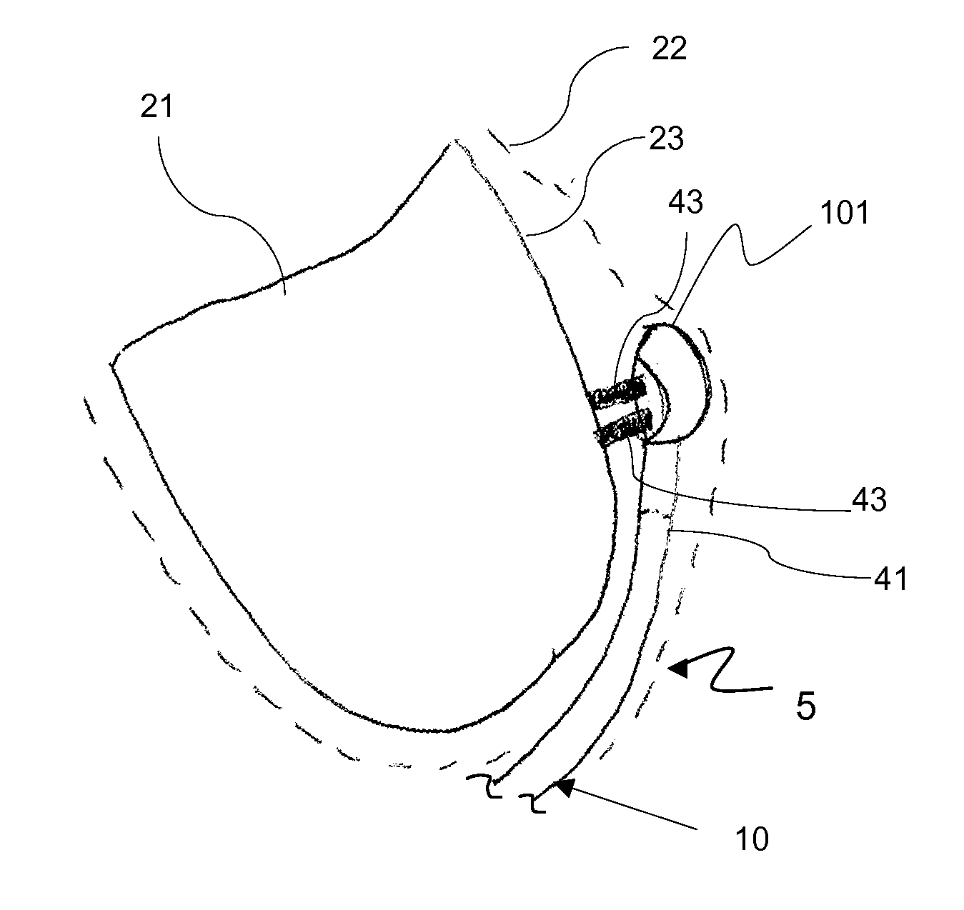
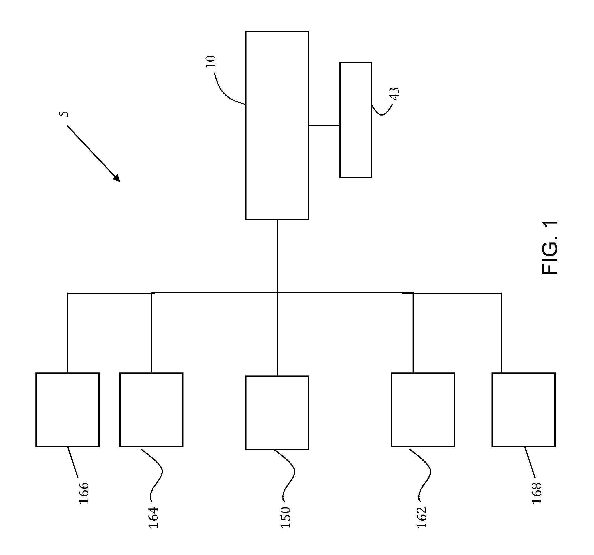
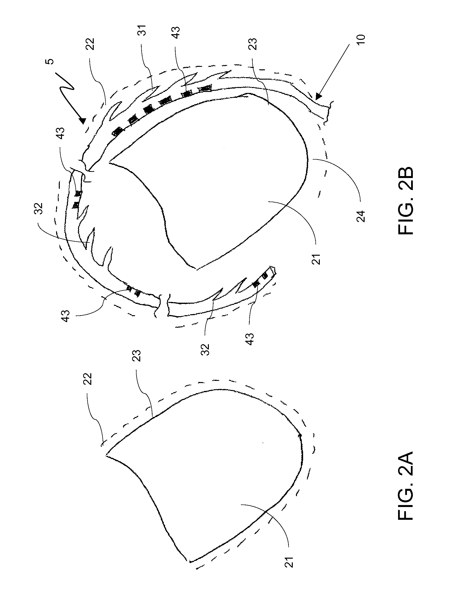
[0020]An aspect of an embodiment or partial embodiment of the present invention (or combinations of various embodiments in whole or in part of the present invention) comprises a method for use with an epicardial pacing catheter. The method may comprise: disposing the epicardial pacing catheter in the middle mediastinum of the thorax of a subject; and pacing the heart at one or more locations with electrical energy from an at least one electrode; and at least partially insulating the electrical energy to allow pacing of the heart without dama

Problems solved by technology

While medical therapy, such as prescription drugs, may benefit a number of patients, side effects prevent some patients from completing therapy.
Moreover, few patients are completely cured of their symptoms.
Unfortunately, due to inherent difficulties in placing left ventricular (LV) leads, less than 15% of eligible patients are able to receive this device.
Unlike the RV, the electrical lead can not be placed directly into the LV due to the unacceptably high risk of stroke.
However, in procedures conducted at the inventors' high volume university hospital, 20% of patients have been found to have a very difficult access to the CS, resulting in an abandonment of the procedure.
Worse still, many of these patients have multiple areas of dead heart tissue, so even if a lead can be placed within a vein, it might not pace the heart.
All of these limitations result in an unpredictable procedure time, making it difficult for hospitals and doctors to plan the operation.
Both the Ncontact® and Heartlander® tools, which are not designed to pace, require surgical incisions.
There are two significant barriers to widespread application of these surgical techniques.
First, surgical procedures are generally more invasive and require longer recovery times. Second, most cardiologists consider it the standard of care to attempt an initial placement of a lead via CS access; only after that fails is surgery considered.
No reference discloses the conceptual arrangements for an integrated cardiological device for epicardial pacing.

Method used


Image

  • Steerable epicardial pacing catheter system placed via the subxiphoid process
  • Steerable epicardial pacing catheter system placed via the subxiphoid process
  • Steerable epicardial pacing catheter system placed via the subxiphoid process

Examples


example no.1

Example No. 1

[0279]Step 1—Access and place a guidewire in the pericardial space using our EpiNeedle Access system.

[0280]Step 2—Use a sheath, preferably our EpiSheath, or a general long 8 Fr sheath to place over the guidewire and maintain access.

[0281]Step 3—Place the lead of the subject invention with handle though the sheath.

[0282]Step 4—Guide the lead in the epicardial space using the two steering points and the sheath under fluoroscopic guidance (although this lead may be guided via one or more other imaging methods to include ICE, CT, MRI, Visual Endoscopy, or Echo Methods). The lead should be advanced along the border of the heart apically to base along the LV. Once it crosses the AV groove to the LA it should be deflected downward and advanced through the transverse sinus. Once across the transverse sinus it will need to be deflected up to the SVC and then down to the RA and finally the RV.

[0283]Step 5—Slide the sheath back to the inferior portion of the RV.

[0284]Step 6—At thi...


PUM


Abstract

The epicardial pacing system and related method includes an epicardial catheter configured to be disposed in the middle mediastinum of the thorax of a subject for use in electrical pacing of the heart at one or more locations on the epicardial surface. The epicardial pacing catheter may include at least one electrode whereby the electrode is insulated on at least one side to allow pacing of the heart without damage to adjacent anatomical structures.

Description

RELATED APPLICATIONS[0001]The present invention claims priority from U.S. Provisional Application Ser. No. 60 / 986,786, filed November, 09, 2007, entitled “Passive Fixation, Steerable Epicardial Lead to be Placed via the Subxiphoid Process for Pacing Left Ventricle, Right Ventricle, Right Atrium and Left Atrium and Cardiac Defibrillation,” and U.S. Provisional Application Ser. No. 61 / 023,727, filed Jan. 25, 2008, entitled “Steerable Epicardial Lead to be Placed via the Subxiphoid Process for Left Ventricular Pacing and Related Method;” the disclosures of which are hereby incorporated by reference herein in their entirety.[0002]This application is related to PCT International Application No. Serial No. PCT / US2008 / 056643, filed Mar. 12, 2008, entitled, “Access Needle Pressure Sensor Device and Method of Use,” the disclosure of which is hereby incorporated by reference herein in its entirety.[0003]This application is related to PCT International Application No. Serial No. PCT / US2008 / 056...

Claims


Application Information

Patent Timeline
IPC IPC(8): A61N1/05A61B17/00
CPCA61N1/0587
Inventor MAHAPATRA, SRIJOYGILLIES, GEORGE T.
Owner UNIV OF VIRGINIA ALUMNI PATENTS FOUND
Learn More