Feed-forward method for repeatable runout cancellation

a repeatable runout and feedforward technology, applied in the field of magnetic recording devices, can solve the problems of non-repeatable runout, inability of the servo mechanism to completely correct, and inability of the closed loop servo mechanism to adequately correct the misalignment of the transducer

Inactive Publication Date: 2010-09-23
HEADWAY TECH INC
View PDF13 Cites 8 Cited by
  • Summary
  • Abstract
  • Description
  • Claims
  • Application Information

AI Technical Summary

Benefits of technology

[0021]It is a first object of this invention to minimize the effects of repeatable runout (RRO) in a hard disk drive.
[0022]It is a second object of the present invention to achieve the first object by applying a simple algorithm that provides good performance while requiring reduced processor resources and a smaller number of necessary computations.
[0024]It is a fourth object of the present invention to provide a method of significantly reducing the computational convergence time by dividing the surface of the disk into a plurality of zones, with each zone having its own array of feed forward compensation values.
[0026]In FIG. 3, rectangular boxes schematically represent electromechanical actions within a functioning HDD that includes the RRO correcting mechanisms of the present invention. These actions are implemented through the closed loop servo mechanism (labeled “controller”) (60), by use of the stored feed-forward algorithm (50), whose operation will be explained below, so that the operation of the “plant” (200), representing the actuator / transducer / spindle-drive, etc. of the HDD, can be effectively controlled.
[0028]The position signal (75) is subtracted from the target position (70) at the summing junction (90) to create a PES (80) (difference between where you want to be and where you are), which is fed into the controller (60) to implement the current correction at the current wedge, and also into the feed-forward algorithm (50) to compute the correction term to be applied at the following wedge. The PES so generated, represents the total misalignment of the transducer that results from all perturbations to the track, RRO and NRRO. In a prior art HDD, which does not include the feed-forward mechanism of the present invention, the controller would produce a servo compensation signal that would not remove the influence of RRO from the total source of misalignment. We shall, in effect, now want the RRO portion to be “ignored” or compensated for, which is the task of the feed-forward algorithm (50). It is to be noted that for use in the computational portion of the algorithm, which is meant to eliminate the RRO portion of the PES, the PES may be computed as the result of averaging position measurements at a particular servo wedge over some selected number of complete disk rotations. Such an average will substantially eliminate the random effects of NRRO, so that the PES value used for correction purposes will be correcting the RRO effects without the NRRO perturbations.

Problems solved by technology

Thus, if the signal sent from the transducer indicating its deviation from the centerline is a complicated oscillatory waveform (as a function of deviation vs. servo wedge location), the closed loop servo mechanism will be unable to adequately correct the misalignment of the transducer.
Other reasons for such transducer oscillations include factors such as disk slippage, disk warpage and even poorly written servo data.
The problem caused by RRO is due to the fact that the HDD transducer is trying to follow the motion of that point.
Another source of positional error is called non-repeatable runout (NRRO), which is caused by various random and environmental effects on the motion of the disk and which is not easily eliminated.
However, if the RRO exceeds some predetermined tolerance defined by the manufacturing parameters of the disk drive, then the servo mechanism is incapable of completely correcting for it and the disk drive will not operate properly.
As compared to the method of the present invention to be described below, this previous method was computationally intensive, utilized much storage capacity and was time consuming.
Smith is particularly concerned with correcting for PES outliers, whose extreme values can adversely affect attempts to compensate for RRO.

Method used


Image

  • Feed-forward method for repeatable runout cancellation
  • Feed-forward method for repeatable runout cancellation
  • Feed-forward method for repeatable runout cancellation

Examples


Embodiment Construction

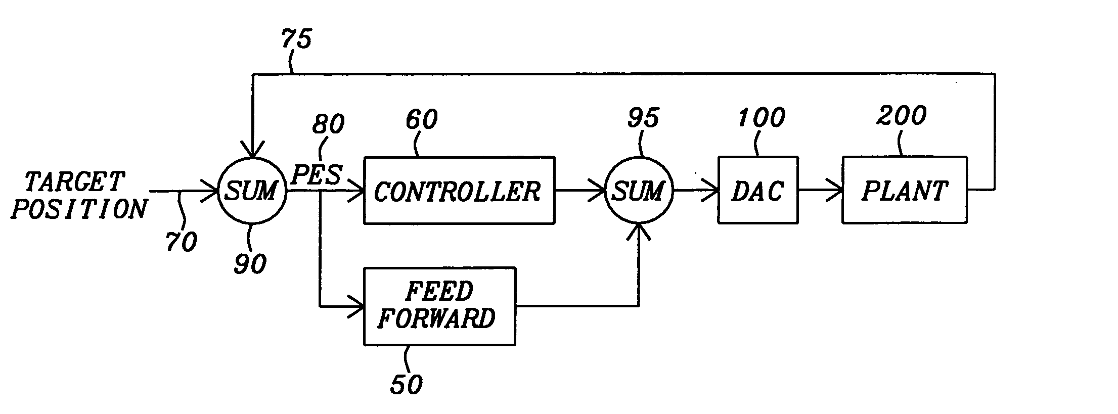
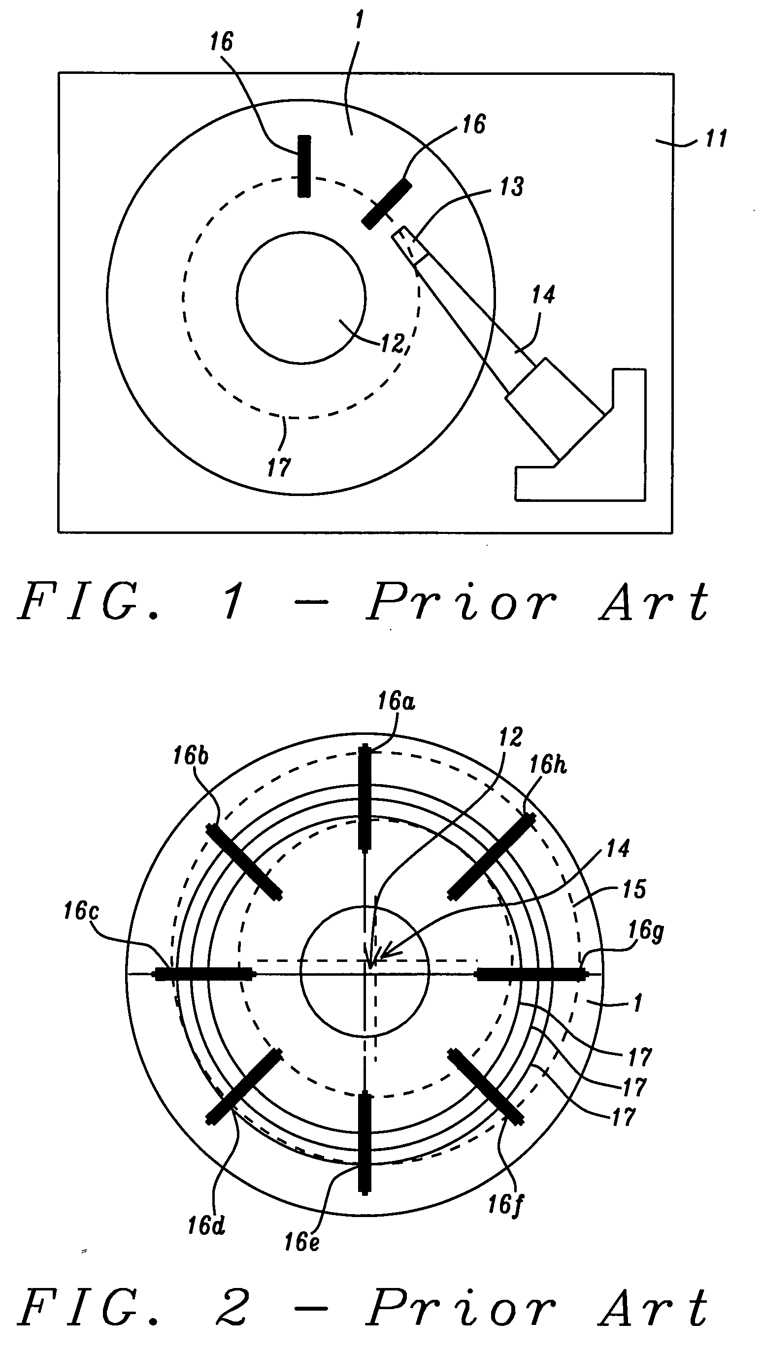
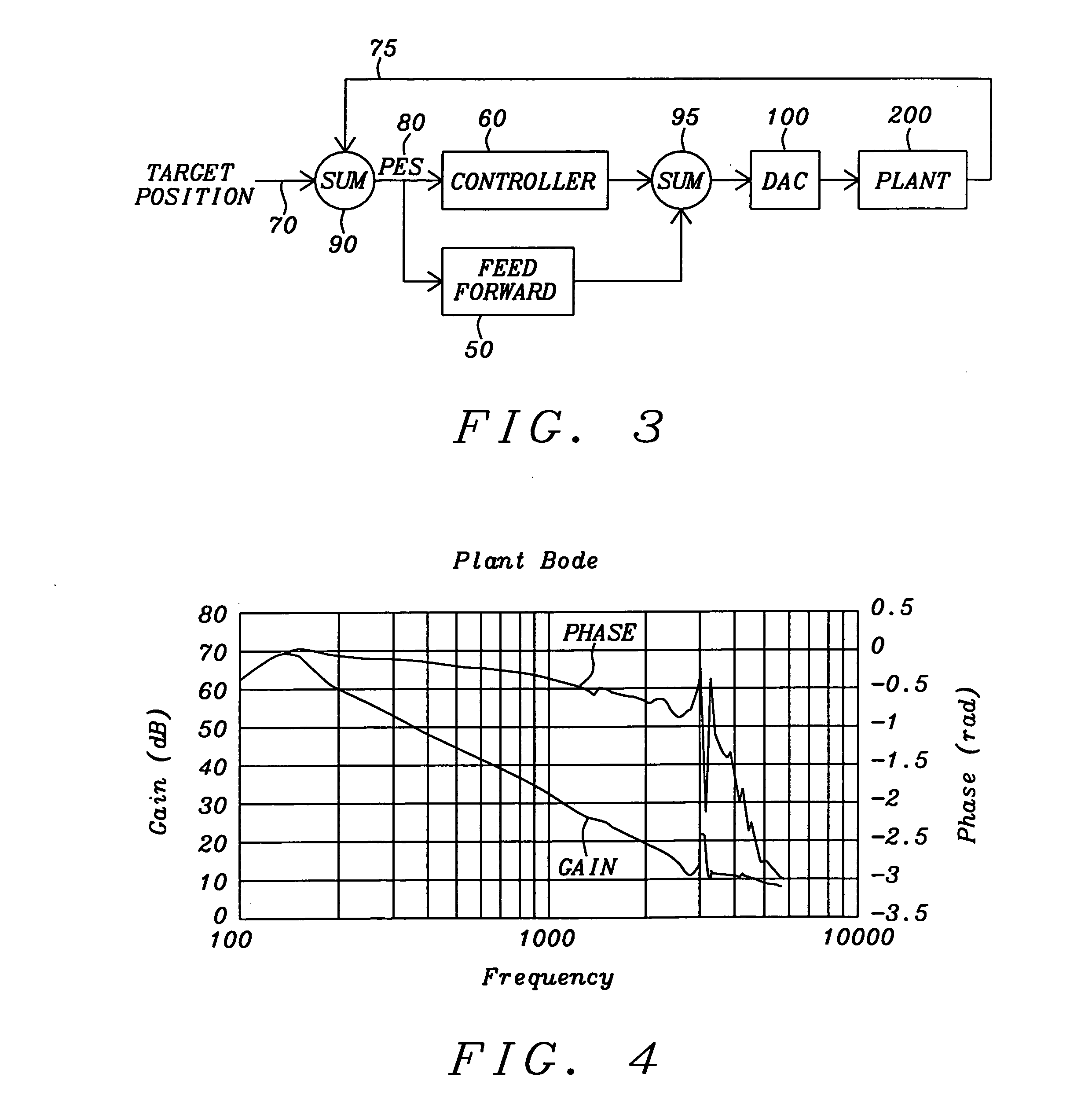
[0046]The present invention teaches a method of operating a hard disk drive (HDD) using disks having a plurality of substantially radially concentric annular tracks, in each of which there is embedded servo track information within some number of regularly spaced wedges of small angular width. Note, this number will be denoted “wpr”, for “wedges per revolution”, in the code written below.

[0047]The information stored within these wedges is used to align a read / write transducer relative to a desired radial position on a track (the “target” position). The method of the invention provides a quick and simple mechanism for making repeatable runout (RRO) corrections at each servo wedge location for the chosen disk tracks (e.g. while at a wedge denoted “n”) and computing new such corrections while at that servo wedge and feeding these corrections forward to be accessed and used at the next servo wedge (e.g. a wedge denoted “n+1”). In this way, the PES of the read / write transducer, which inc...


PUM

PropertyMeasurementUnit
angular widthaaaaaaaaaa
rotational frequencyaaaaaaaaaa
phase performanceaaaaaaaaaa

Abstract

A magnetic hard disk drive includes a method for eliminating that portion of track following error by a read / write transducer that is caused by repeatable runout of the disk tracks. The repeatable runout is eliminated by application of an iterative algorithm that calculates feed-forward correction terms based on gain coefficients iteratively calculated from the amplitude and phase portions of a Bode plot characterizing the system. The corrective coefficients can be inserted into the hard disk drive at a summing junction that redefines the centerline of the track, or at a summing junction that causes the actuator to follow the repeatable runout and make non-repeatable runout corrections relative thereto.

Description

BACKGROUND OF THE INVENTION[0001]1. Field of the Invention[0002]This invention relates generally to a magnetic recording device in which there is a rotating magnetic disk on which servo information has been written to guide the positioning of a read / write transducer. More particularly, it relates to such a device wherein the use of the servo information has been optimized to cancel the effects of repeatable runout (RRO).[0003]2. Description of the Related Art[0004]As shown schematically in FIG. 1, a typical magnetic disk (1) mounted on a rotatable spindle (12) in a hard disk drive (HDD) (11) is characterized by radially concentric, annular, circular tracks (17) on which data can be written and from which data is read by means of a read / write transducer (13) mounted on an actuator assembly (14). In order to for the read / write transducer to accurately follow such a circular track while executing reading and writing operations, i.e., to maintain a fixed radial position over the centerl...

Claims


Application Information

Patent Timeline
Patent Type & Authority Applications(United States)
IPC IPC(8): G11B5/596
CPCG11B5/59627
Inventor DROUIN, DAVIDWAHNG, BILLY
Owner HEADWAY TECH INC
Why Eureka
Try Eureka