There are many technologies that are able to store and regenerate electrical energy, but few of these methods are able to do so cheaply enough to be economically useful in applications that are connected to large scale
system such as utilities' electricity grids.
All the few currently available technologies that are able to perform economically are limited in their usefulness by various geographical, geological, and / or topological requirements that limit their ultimate achievable capacity, and their proximity to potential users.
While their are numerous generation technologies in the
market place that can produce large quantities of
usable electricity without producing CO2 and other pollutants as a byproduct, none of the currently known and readily expandable solutions is able to arbitrarily increase or decrease its output to match user demand.
Technologies based on wind, solar, and tidal energy conversion are only able to generate electricity when these energy sources are available.
Nuclear power is notoriously hard to rapidly increase and decrease, running far more efficiently when operated at a steady-state output.
Because of these temporal limitations, these technologies are only able to serve a small portion of total electricity demand, and must rely on fossil-fuel generation to provide power at critical times. In order for these technologies to economically grow as a percentage of total
system generation capacity they require very large increases in the capacity to store and regenerate electricity.
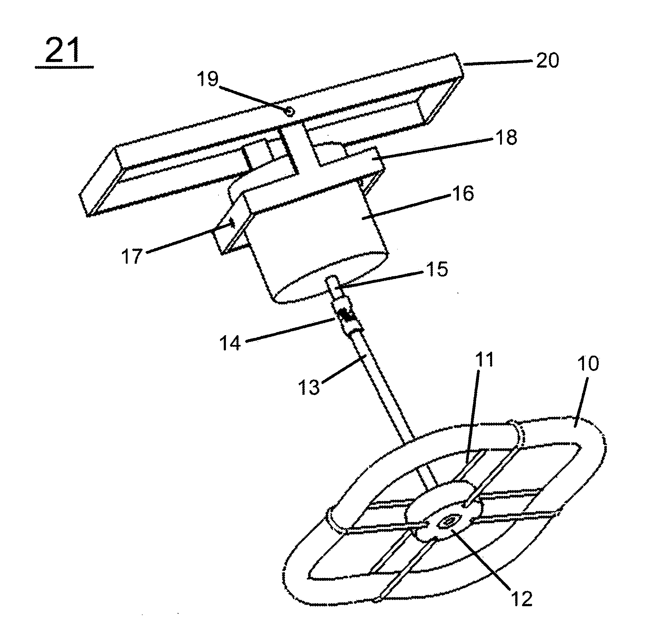
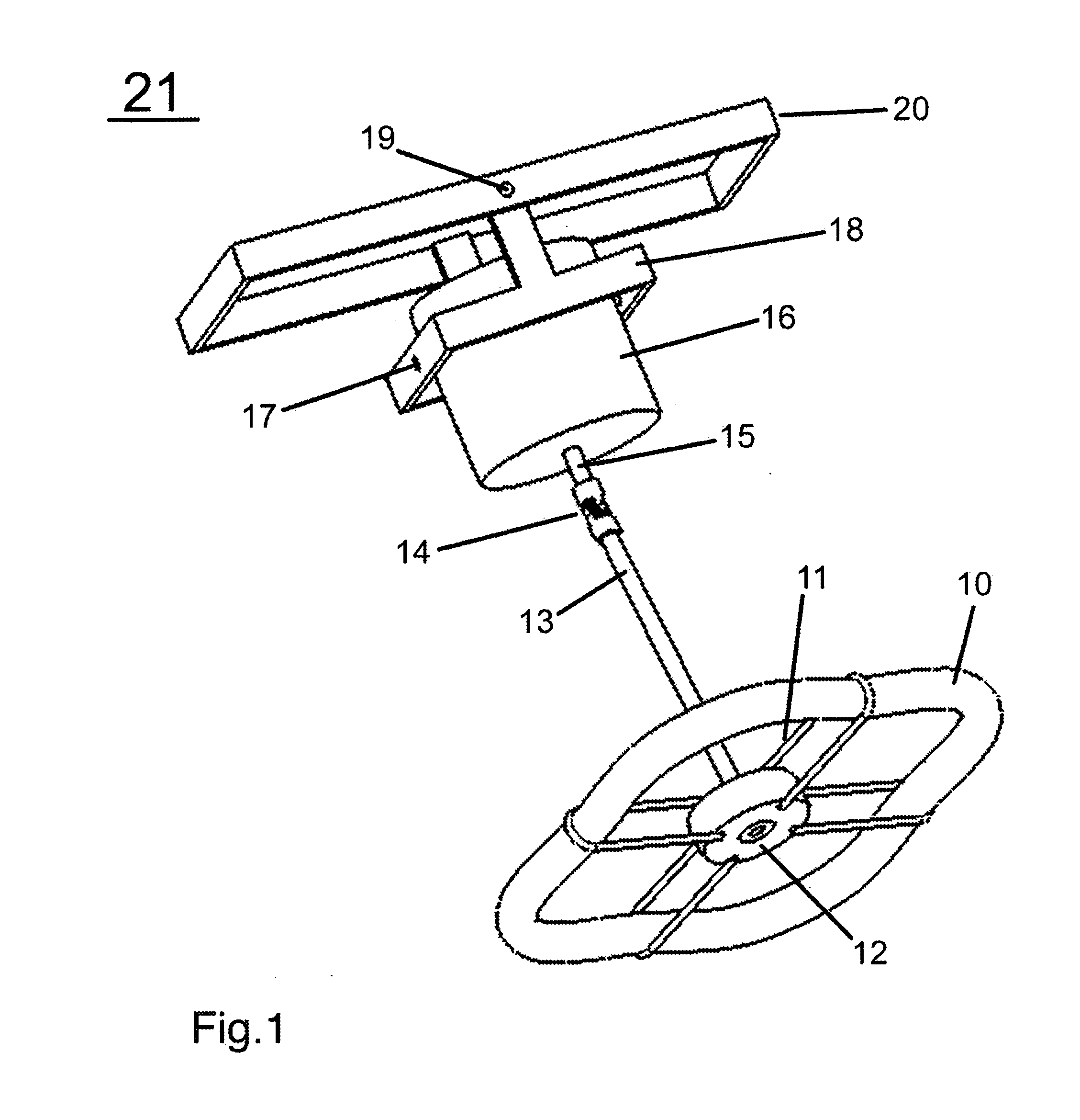
There are a multitude of design issues that must be considered in the construction of a flywheel.
In flywheel rotor systems that are rigid or semi-rigid, these differences can cause large shear stresses to develop between portions of the flywheel rotor.
These stresses can cause the destruction of the flywheel rotor.
This problem is the subject of much work in the flywheel field.
The device was not fully tested however, before the project was disbanded.
The device suffers from some crucial limitations that preclude its use in as a deployable
energy storage solution as described.
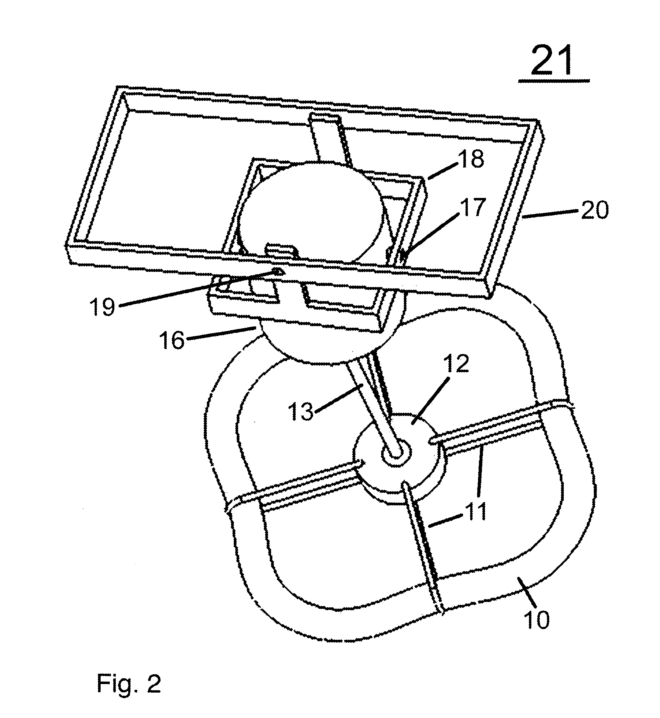
The most critical limitation is that the system becomes wildly unstable if and when the supporting ropes are allowed to untwist.
When the supporting ropes become unwound, the flywheel rotor loses its self-balancing and self-stabilizing properties and becomes wildly unstable, a condition that is not acceptable for deployable systems.
While the period of
instability in such an instance is often quite short and generally will not
crash the system, it is violent and creates considerable uncontrolled stresses on the system that are not desirable in any
high availability application.
The Vance flywheel is also critically limited in the amount of torque that can be applied to the system.
At some point on this continuum the flywheel becomes unstable either from the loss of length or from the loss of flexibility.
From this it may be seen that there is a strict and rather low limit to the amount of torque that one can apply to the system before it becomes unstable.
Apply too much torque and the twisted ropes will twist up on themselves again and again shortening their
effective length with each new layer of twist until the flywheel becomes more or less rigidly attached to the motor / generator and loses its ability to self-balance.
The flywheel becomes wildly unstable.
This torque limitation is quite significant because it limits the rate at which power can be injected into and extracted from the system, limiting the system's utility.
This can also be a safety issue in cases where it is desirable to
discharge the flywheel as rapidly as possible.
This in turn dramatically increases the amount of energy that can be put into or drawn off of the system in a given period of time.
Because the
spoke or
core system will not allow the fibers to fall into the balanced circular form that it they would naturally prefer to, they experience a compressive force that increases with the flywheel rotor's speed of rotation.
These “bare filament” or “sub-circular” flywheel rotors as discussed can be balanced reasonably well, but shifting of the filaments with respect to each other limits their utility in standard rigidly supported flywheel systems as these flywheel rotors are dynamic in and of themselves and so will tend to lose balance as the system is cycled.
Additionally, these flywheel rotors require relatively expensive materials and techniques for the fabrication of the
spoke 70, hub 73, or core.
Inexpensive materials such as plywood have been successfully tested by Rabenhorst, but their reliability was deemed too low, and their tenancy to “out-gas” into the vacuum environment requires the system to incorporate an active vacuum
maintenance system such as a
diffusion,
ion, turbo, or
sorption pump at additional fabrication expense and energy overhead.
Such a system for active maintenance of vacuum is also a wear and / or maintenance item.
Many ways of injecting energy into the system, and extracting the energy, are inefficient, expensive, or bulky.
Some of these ways are poorly suited to the physical environment to be employed here (vacuum).
Many of the previously mentioned motor / generator systems, while
usable in this system are not optimal for one of more of these reasons.
But these motors, while extremely useful and widely adopted, suffer several disadvantages in the flywheel application that can be avoided with a different approach to the motor / generator problem.
Those disadvantages are energy dissipation and high expense.
Firstly, all bearing systems that are not “non-contact” systems will have surfaces that are in contact with one and another and will generate frictional losses when the bearing is spun.
The brushes universally cause frictional losses in the system.
Because electro-magnetic motors must use coils of wire to create the electro-magnets that are fundamental to their operation,
joule heating is a unavoidable result.
Joule heating can be minimized at a given
power level by the use of a thicker wire, but this generally results in greater expense and this solution is limited by the geometry of the
motor system.
Hysteresis losses occur in the soft
magnetic core materials that are used in electromagnetic motors to increase magnetic power and concentration.
It can be entirely avoided by designs that do not use soft
magnetic core materials which are generally called “air-core” designs, but these designs require significantly more amp-turns in their coils in order to generate the same power levels as standard cored motors and so are generally subject to significantly higher
joule heating losses and / or expense.
Despite the usefulness of eddy currents in many designs, these currents can be quite substantial and are subject to
joule heating and are hence a source of losses.
Joule,
hysteresis, and eddy-current losses though will be tough to significantly reduce beyond a certain level if electro-magnetic motor / generators are used.
But these sources of loss are still very much present when the motor / generator is active, and the costs of the materials and fabrication methods required to construct such a motor-generator are prohibitive given the current state of the art in manufacturing technique and prevailing market prices for materials.
Even though these designs generally are unable to meet electro-magnetic designs in terms of power /
unit volume which is a very important metric in many applications, these devices if properly designed can meet or beat electro-magnetic solutions in power /
unit cost which is of great significance to the flywheel application.
Because in the flywheel application is is desirable to reduce
windage loses and therefor desirable to run the system in a vacuum,
corona is not an
effective method of transmitting charge and power.
Obviously the friction that such a brushed system would create is undesirable.
