Hulling device

Active Publication Date: 2010-09-23
CHEFN
View PDF10 Cites 6 Cited by
  • Summary
  • Abstract
  • Description
  • Claims
  • Application Information

AI Technical Summary

Benefits of technology

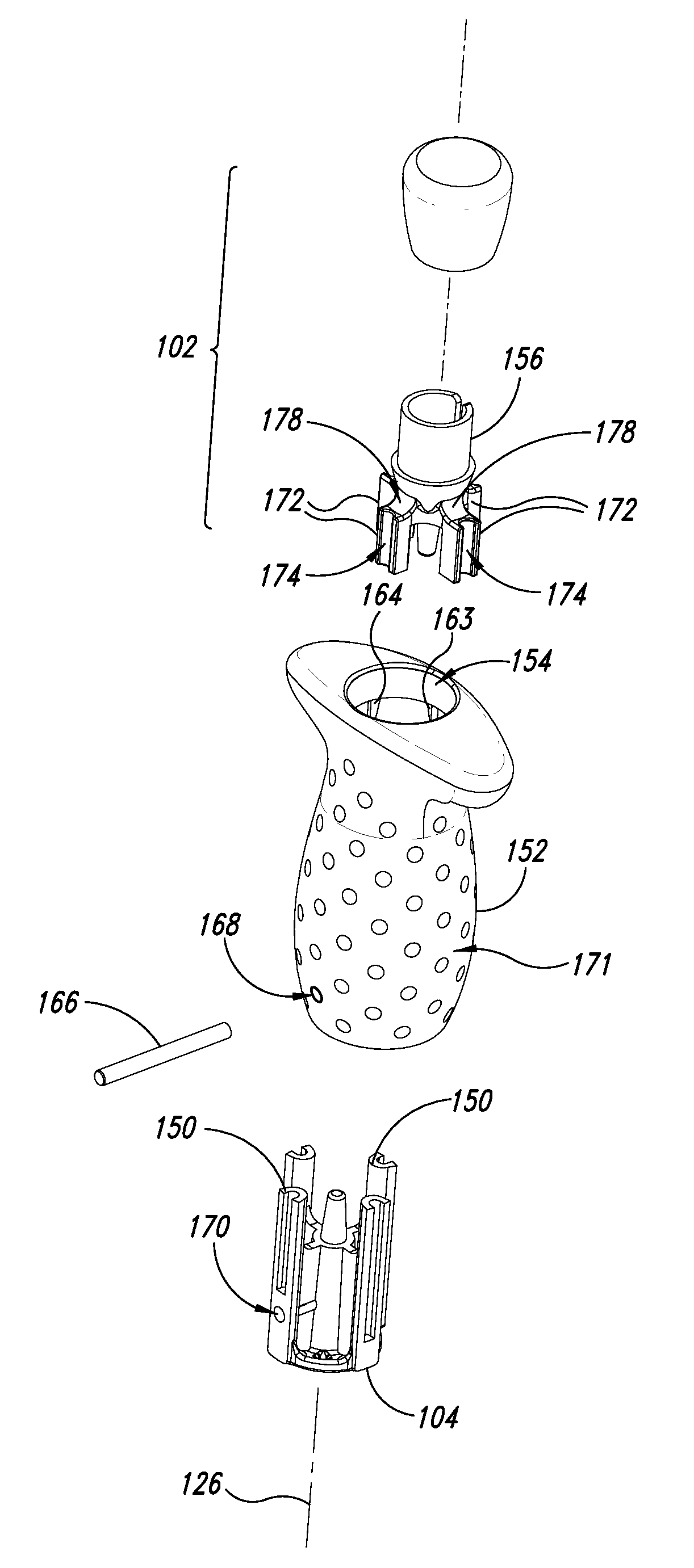
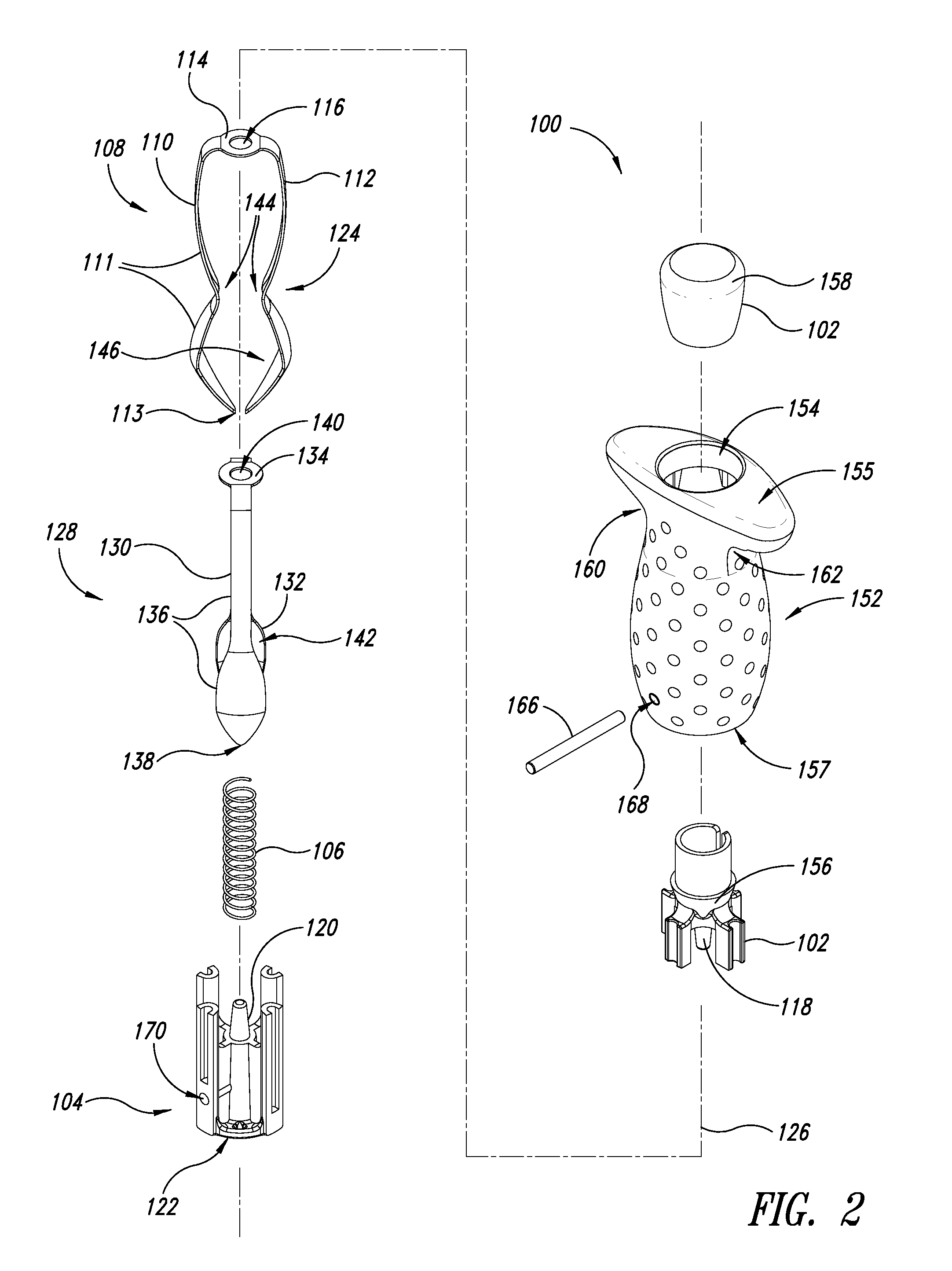
[0007]According to one embodiment, a hulling device includes a pushing member configured to be selectively actuated, a cap spaced from the pushing member and including a plurality of contact regions, the pushing member being moveable with respect to the cap, a spring having a first end coupled to the pushing member and a second end coupled to the cap, and at least a first nipper. The first nipper includes a first base, a first nipping member and a second nipping member, the first base coupled to the pushing member, the first and second nipping members extending from the first base toward and beyond the cap, and respectively having a tip and a sliding region between the tip and the first base. The sliding regions of the first and second nipping members are slidably positioned adjacent respective contact regions of the cap, the sliding regions respectively mutually shaped with the contact regions to facilitate movement of the respective tips away from each other as the sliding regions slide against the contact regions upon actuation of the pushing member.
[0008]According to one aspect, the hulling device further includes a second nipper including a second base, a third nipping member and a fourth nipping member, the second base coupled to the pushing member, the third and fourth nipping members extending from the second base toward and beyond the cap, and respectively having a tip and a sliding region between the tip and the second base. The sliding regions of the third and fourth nipping members are slidably positioned adjacent respective contact regions of the cap, the sliding regions respectively mutually shaped with the contact regions to facilitate movement of the respective tips away from each other as the sliding regions slide against the contact regions upon actuation of the pushing member.
[0009]According to one aspect, the hulling device includes a main body including a first end, a second end, and an opening extending from the first end to the second end, the main body housing at least a portion of the pushing member, cap, spring, and / or first nipper, the opening facilitating access to the pushing member toward the first end, the tips of the at least first nipper projecting beyond the opening toward the second end during use.
[0013]According to one embodiment, a hulling device includes a longitudinal axis, a cap having a peripheral edge, a pushing member opposing, and moveably positioned with respect to, the cap along the longitudinal axis, and a spring having a first end coupled to the pushing member and a second end coupled to the cap. The hulling device further includes first and second nippers. The first nipper has a first base, a first nipping member and a second nipping member, the first base coupled to the pushing member, the first and second nipping members extending from the first base toward the cap, and respectively having a tip and a contoured region between the tip and the first base, the contoured regions slidably engaging respective peripheral regions of the cap, and having a non-planar profile to facilitate movement of the respective tips away from each other as the contoured regions slide against the peripheral regions. Similarly, the second nipper has a second base, a third nipping member and a fourth nipping member, the second base coupled to the pushing member, the third and fourth nipping members extending from the second base toward the cap, and respectively having a tip and a contoured region between the tip and the second base, the contoured regions slidably engaging respective peripheral regions of the cap, and having a non-planar profile to facilitate movement of the respective tips away from each other as the contoured regions slide against the peripheral regions.

Problems solved by technology

One preparation task that is time-consuming is hulling food items.
However, such methods remove more than what is required.
For example, in the case of strawberries, edible portions are removed along with the hull when a knife is used, resulting in wasting useful portions of the strawberry.
Such elementary methods are also cumbersome and time-consuming, and pose a risk of injury to a user.
Other hulling devices or tongs are difficult to manipulate, making it hard to hull a large number of food items in a short amount of time and typically remove more of the food item than desired.
Other existing devices that are more expedient to use include cylindrical coring portioners that remove a fixed volume of the food item regardless of the size of the food item, and therefore, result in wasting usable portions of the food item.
These devices are also difficult to clean, as residue builds up inside the core-removing cylinder, which is not easily accessible.

Method used


Image

  • Hulling device
  • Hulling device
  • Hulling device

Examples


Embodiment Construction

[0022]FIG. 1 illustrates a hulling device 100 according to one embodiment including a pushing member 102, which allows a user to operate the hulling device, as discussed in detail below. As illustrated in FIG. 2, the pushing member 102 is shown disassembled into two parts. During operation, the two parts are assembled, as shown in FIG. 3. The hulling device 100 includes a cap 104 spaced from the pushing member 102, and a spring 106 having a first end configured to be coupled to or abutted against the pushing member and a second end configured to be coupled to or abutted against the cap, as shown in one aspect in FIG. 3. As illustrated in FIG. 2, the hulling device 100 further includes at least a first nipper 108 having a first nipping member 110, a second nipping member 112, and a base 114. The first and second nipping members 110, 112, each include a body 111 and a tip 113, the body being located between the tip and the base.

[0023]The base 114 is configured to be coupled to or abut...


PUM


Abstract

A hulling device includes a cap, a pushing member, a spring between the cap and pushing member, and at least one nipper having two nipping members coupled to the pushing member and extending toward the cap. The nipping members are mutually shaped with the cap and slide contiguous respective contact regions of the cap to separate tips of the nipping members upon actuation of the pushing member. The separated tips can be inserted in a food item, such as a strawberry, and twisted and pulled to hull the food item. The user can release the pushing member when the tips are in the food item to improve gripping and severing the hull. The hulling device can also include a main body housing at least a portion of the pushing member, cap, spring, and first and second nippers, the main body being coupled to the cap, the pushing member, or both.

Description

CROSS-REFERENCE TO RELATED APPLICATION[0001]This application claims the benefit under 35 U.S.C. §119(e) of U.S. Provisional Patent Application No. 61 / 210,654 filed Mar. 20, 2009, incorporated herein by reference in its entirety.BACKGROUND[0002]1. Technical Field[0003]The present disclosure is related to kitchen and / or food preparation tools, and more particularly, to a device for hulling a food item, such as a fruit.[0004]2. Description of the Related Art[0005]In the culinary arts, efficiency and presentation are both crucial to preparation of food items. One preparation task that is time-consuming is hulling food items. Various food items are hulled for different purposes, for example, to remove unwanted or uneatable portions, to provide an aesthetic appearance, or to achieve a shape that facilitates placing other items in the hulled region. One food category, which is frequently hulled, includes fruits, such as strawberries. Conventional methods of hulling include, in the simplest...

Claims


Application Information

Patent Timeline
IPC IPC(8): A23N7/00A23N15/02
CPCA47J43/281
Inventor HOLCOMB, DAVID A.HULL, DAVID
Owner CHEFN
Why Eureka
Try Eureka