Eureka AIR delivers breakthrough ideas for toughest innovation challenges, trusted by R&D personnel around the world.

Manually Actuable Liquid Dispensing Razor

Active Publication Date: 2010-09-23
THE GILLETTE CO
View PDF72 Cites 86 Cited by
  • Summary
  • Abstract
  • Description
  • Claims
  • Application Information

AI Technical Summary

Benefits of technology

[0009]Certain implementations of the invention may include one or more of the following features. Typically, the fluid is stored in the cavity in a sachet, which can be replaceable or refillable. The fluid dispensing member may be integrally formed with the cartridge connecting structure. The fluid dispensing member may extend to or adjacent to the front surface of the housing allowing for direct contact to a user during shaving. The dispensing end of the fluid dispensing member may engagably mate with the housing. In an embodiment, the dispensing channel includes at least two openings at the dispensing end to provide for multiple dispensing points. To prevent the fluid from leaking, any or all of the openings may comprise a check valve.

Problems solved by technology

Most consumers find this type of preparation to be rather inconvenient because of the need for multiple shaving products, e.g., a wet razor and a skin preparation product, as well as the undesirable necessity for multiple application steps during the wet shaving process.
Many of these types of razors that are capable of conveying a liquid to the skin surface are unfortunately plagued by a number of problems.
For instance, the inner workings of the razors tend to be cost prohibitive from a large scale manufacturing standpoint.
Additionally, there are safety and performance issues that are constantly experienced due to microbial growth with the reservoir due to the continued exposure of a portion of the remaining liquid to air.
This exposure of the liquid to air may oftentimes result in clogging of the razor's inner workings by the liquid resulting in a nonperforming shaving product.

Method used


Image

  • Manually Actuable Liquid Dispensing Razor
  • Manually Actuable Liquid Dispensing Razor
  • Manually Actuable Liquid Dispensing Razor

Examples


Embodiment Construction

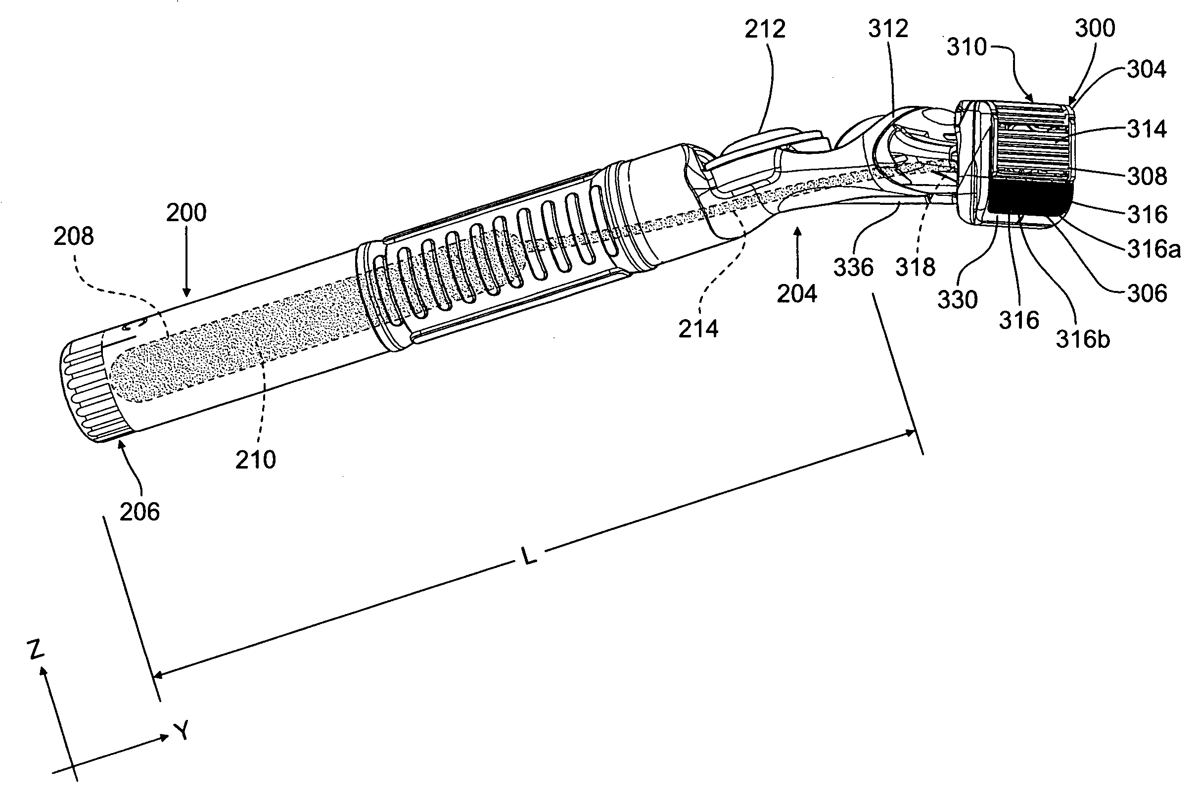
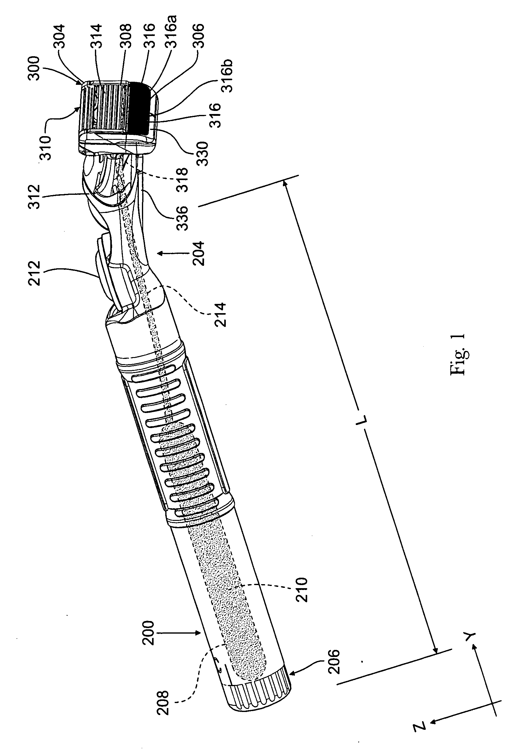
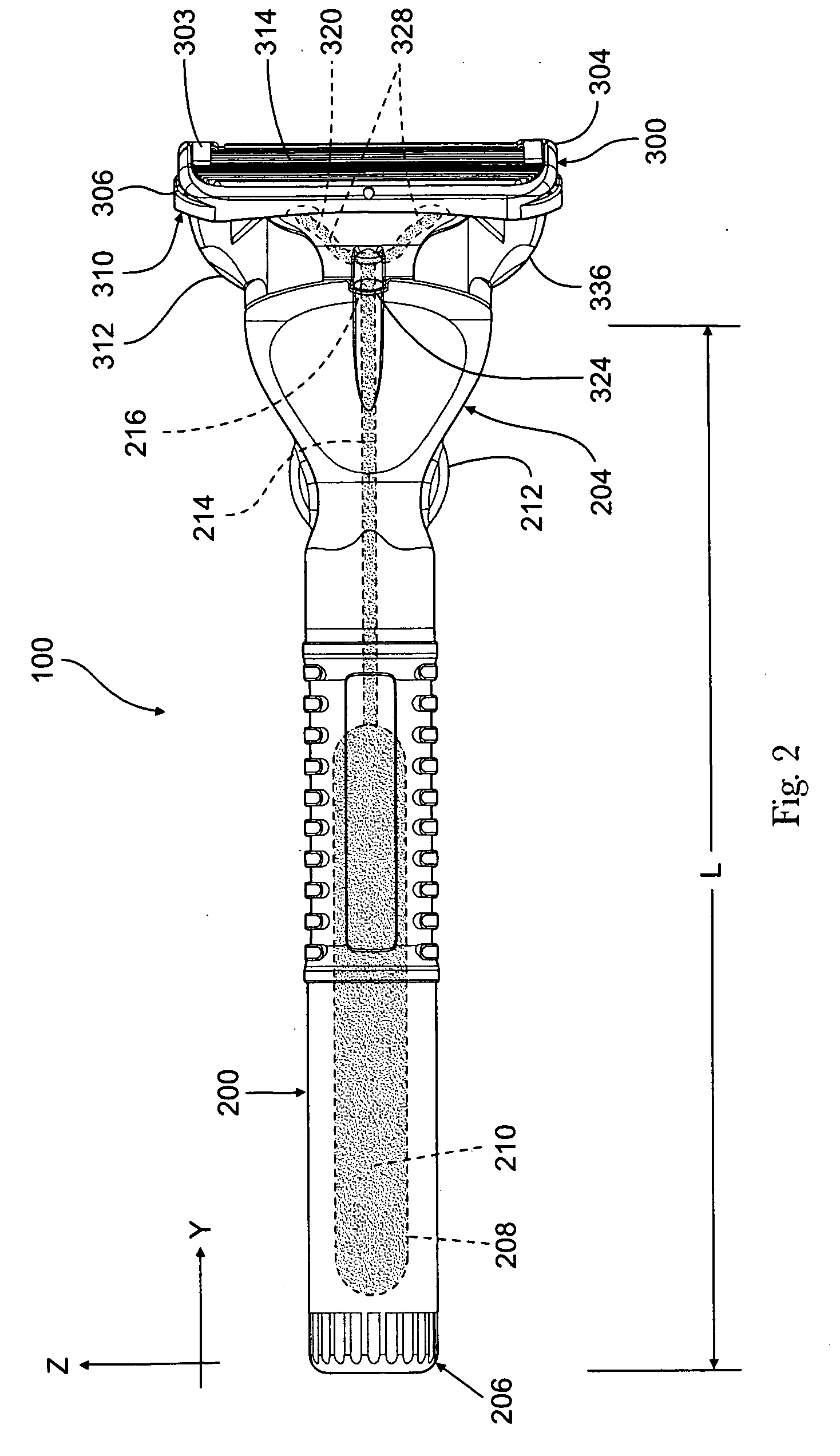
[0019]FIGS. 1-5 show a wet shaving razor (100) for dispensing a fluid during shaving that includes a handle (200) and a razor cartridge (300). The handle (200) has a length (L) that extends from a proximal end (204) to a distal end (206). The handle also includes a cavity (208) for housing a fluid (210) disposed within the handle (200) and a manually-actuated pump (212) located along the length (L) of the handle (200). The pump (212) is adapted to displace the fluid (210) from the cavity (208) through a supply channel (214) to an opening (216) at the proximal end (204) of the handle (200).

[0020]The manually-actuated pump (212) may include stacked (and substantially flat) components and particularly a movable wall that acts to activate the flow of fluid from the cavity through channel and to the opening. A pump suitable for use in the present invention is disclosed in U.S. Pat. No. 5,993,180. In particular, this well-suited pump includes a pump chamber bounded by the movable wall, an...


PUM

PropertyMeasurementUnit
Forceaaaaaaaaaa

Abstract

The invention features a razor for dispensing a fluid during shaving. The razor includes a handle, a razor cartridge, and a fluid dispensing member joined to the cartridge. The handle includes a cavity for housing a fluid and a manually-actuated pump to displace the fluid from the cavity through a supply channel to an opening at the proximal end of the handle. The razor cartridge includes a cartridge connecting structure attached to the housing, at least one blade positioned in the housing, and an aperture that extends from the rear surface to the front surface of the housing. The fluid dispensing member has a dispensing channel with an opening at a supply end and an opening at a dispensing end. The supply end is configured to engage the opening in the supply channel. The dispensing end projects outwardly and extends to or adjacent to the aperture in the housing.

Description

FIELD OF THE INVENTION[0001]This invention relates to a manually actuable liquid dispensing razor.BACKGROUND OF THE INVENTION[0002]This invention relates to the field of wet shaving which is the process where a razor with one or more sharpened blades is moved along skin to cut hair. When a consumer engages in the wet shaving experience, it is typical to apply a skin preparation, e.g., shaving soap, shaving cream, shaving gel, skin conditioning foam, etc., via a brush or manual application prior to movement of the razor along the skin's surface. Most consumers find this type of preparation to be rather inconvenient because of the need for multiple shaving products, e.g., a wet razor and a skin preparation product, as well as the undesirable necessity for multiple application steps during the wet shaving process. This multi-step process also results in an overall extended shaving experience which most consumers do not prefer given typical morning hygiene routines. It may, however, be ...

Claims


Application Information

Patent Timeline
IPC IPC(8): B26B21/40B26B21/00B26B21/52
CPCB26B21/4018Y10T29/49826B26B21/446
Inventor SZCZEPANOWSKI, ANDREW ANTHONYSALEMME, JAMES LEOSIMMS, GRAHAM JOHNWATTAM, CHRISTOPHER JAMESCLARKE, SEAN PETER
Owner THE GILLETTE CO
Why Eureka
Eureka Blog
Learn More