
Method for managing network components in a network, and a network component

a network and component technology, applied in the field of network components and network components management, can solve the problems of affecting the task of finding network components in other subnets, unable to reach discovery packets which do not reach subnets, and unable to cross the boundaries of subnets. the load of the network caused by additional data exchange should be minimized, and the required computer power is minimal

Inactive Publication Date: 2010-09-16
THOMSON LICENSING SA
View PDF14 Cites 2 Cited by
  • Summary
  • Abstract
  • Description
  • Claims
  • Application Information

AI Technical Summary

Benefits of technology

[0027]If a semi-automatic selection method is applied, the selection is made under the supervision or at least with the help of a user or an administrator. If, for example, a user of the requesting network component intends to print a document, an appropriate printer must first be found in another subnet if such a printer fails to be present in the request subnet. In this case, it is not expedient if the found printer is positioned in any other subnet which is, perhaps, far from the requesting network component. In such cases, it is advantageous if the user or an administrator can specify the subnets in which a printer is to be found.

Problems solved by technology

However, the task of finding network components in other subnets is problematic.
This, however, may result in a discovery packet which does not reach a subnet of a sought-for network component at all.
In these cases, it is entirely impossible for a discovery packet to cross the boundaries of subnets in order to reach other subnets.
However, such a solution is usually not suitable for “plug and play” functionality.
Furthermore, a failure of such a central server may easily give rise to problems.
The method known from EP 1339 190 A2 is to disadvantage in that the information concerning the second subnet and transmitted from the second device to the first device is only current at the time of request.
In this case, it is not expedient if the found printer is positioned in any other subnet which is, perhaps, far from the requesting network component.

Method used


Image

  • Method for managing network components in a network, and a network component
  • Method for managing network components in a network, and a network component

Examples


Embodiment Construction

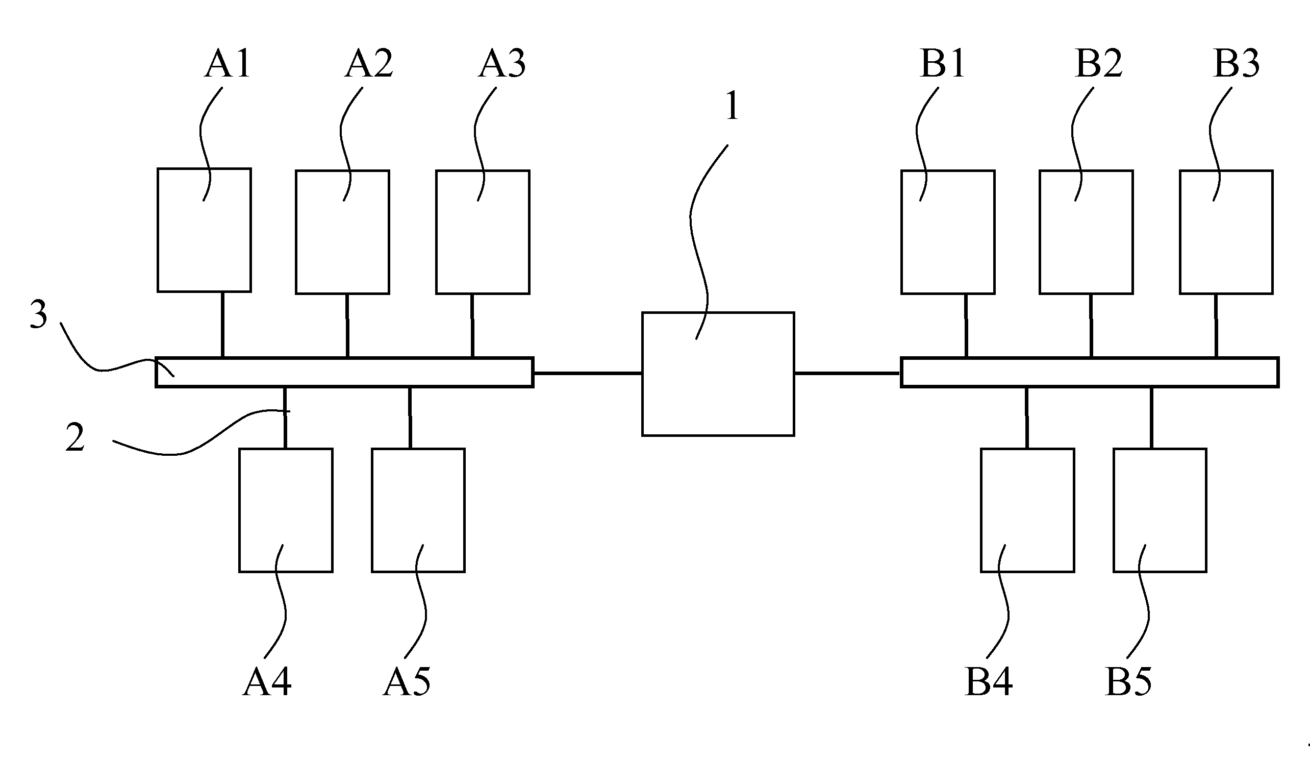
[0034]The FIGURE shows a network which comprises two subnets A, B. In the following, one of the subnets A, B is referred to as request subnet A and the other one as select subnet B. In the request subnet A, a plurality of request network components A1, A2, . . . , An are interconnected by means of data connections 2 via a data bus 3, whereas a plurality of select network components B1, B2, . . . , Bm are interconnected in the select subnet B. The two subnets A, B form independent networks which are connected or “routed” to each other by means of a switching unit or gateway 1 in a data system. That means that it is possible to access one of the subnets A, B from the other one of the subnets A, B, for example by means of a “ping” request.

[0035]Below, a method will be illustrated by means of which a requesting network component A2 in the request subnet A can receive information concerning the select network components B1, B2, . . . , Bm of the select subnet B, for example in order to a...


PUM


Abstract

The invention relates to a method for managing network components in a network comprising a request subnet with request network components and a select subnet with select network components as well as to a network component, wherein the requesting network component out of the request network components of the request subnet transmits a registration request to a selected network component out of the select network components of the select subnet and, based on the registration request, the selected network component transmits information concerning the configuration of the select subnet at the time of registration request to the requesting network component, wherein, based on the registration request, the selected network component transmits further information concerning the configuration of the select subnet to the requesting network component at a later point in time which is chronologically following the registration request.

Description

[0001]The invention relates to a method for managing network components in a network and to a network component.PRIOR ART[0002]By integrating a plurality of electronic devices, networks can be formed in which so-called distributed applications are executed. These are application programs accessing a plurality or all of the electronic devices of the network, wherein said electronic devices serve as network components. The network components may, for example, be a printer, a scanner, a fax machine, or the like, which can be accessed by another network component in the network, for example a personal computer.[0003]Working with distributed applications in networks is facilitated by what is called discovery methods, said methods forming a central technology which must be functioning properly to ensure system acceptance. Discovery methods are methods for discovering and registering new network components in a network as well as for detecting that network components that were previously c...

Claims


Application Information

Patent Timeline
Patent Type & Authority Applications(United States)
IPC IPC(8): G06F15/173
CPCH04L69/28H04L41/12H04L41/00
Inventor HUTTER, INGOWEBER
Owner THOMSON LICENSING SA
Learn More