
Method and device for compensating for a material web offset in material web inspection

a technology of material web and offset, applied in the field of method and device for compensating for material web offset in monitoring and, can solve the problems of complex use of software, and difficult to find identical patterns

Active Publication Date: 2020-06-23
TEXMAG GMBH VERTRIEBS
View PDF9 Cites 0 Cited by
  • Summary
  • Abstract
  • Description
  • Claims
  • Application Information

AI Technical Summary

Benefits of technology

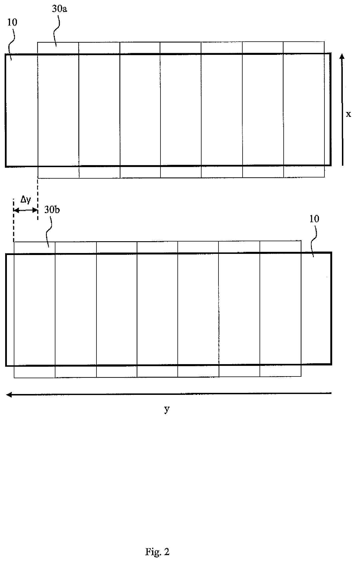
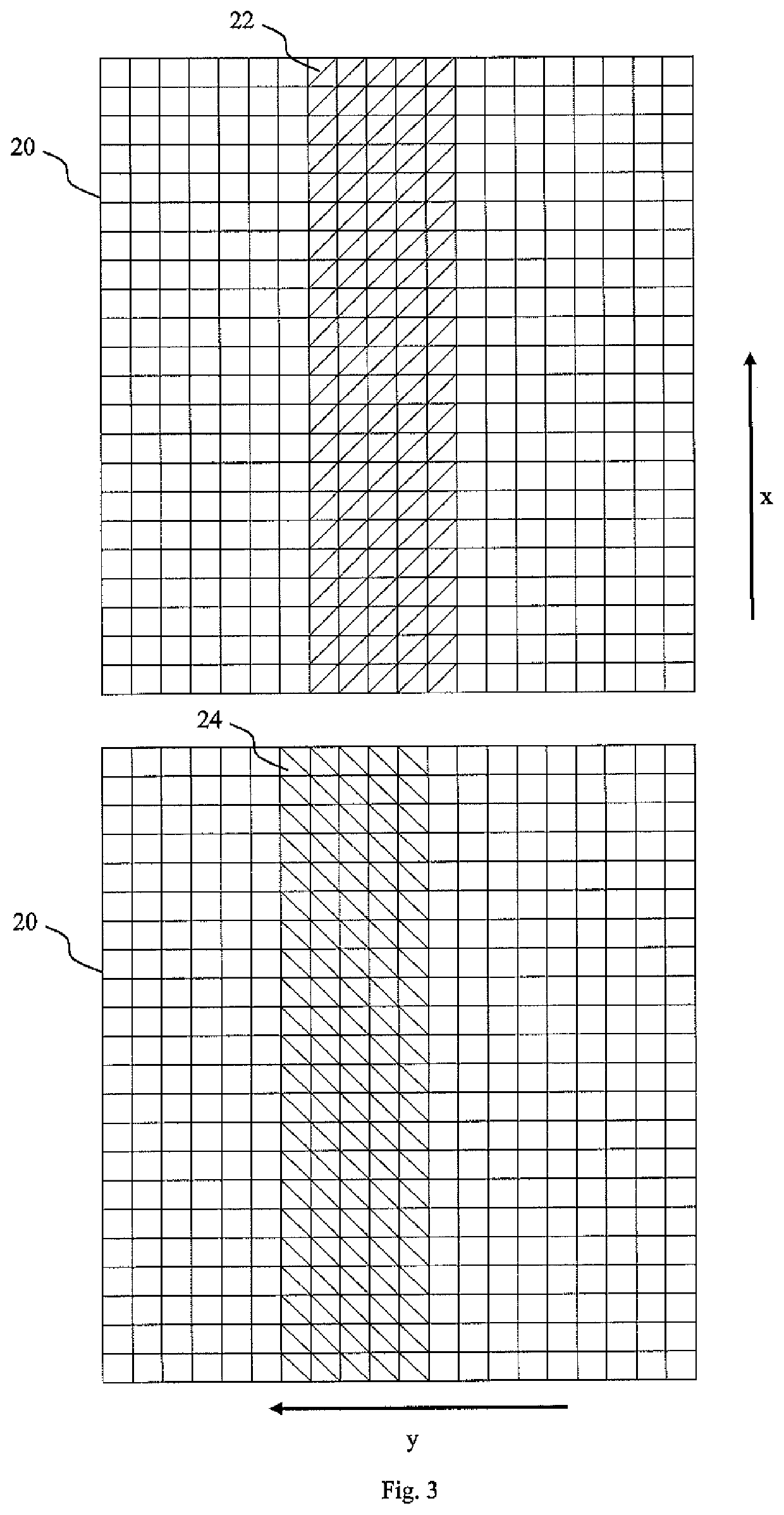
[0007]The dynamic adjustment of the active partial surface used by the matrix chip allows a direct and exact synchronization of two sequences of pictures of a material web and is independent of the characteristics of the material web (which are required, for example, when compensating for the offset using software). As a result of this adjustment, two (or more) sequences of pictures taken at very slightly different times can be directly captured and laid exactly on top of one another. There is therefore no need for any complex and sometimes completely impossible or at least unsatisfactory compensating for any offset in the direction of the material web length in the pictures using software evaluation. The image capture frequency can also be increased by reducing the size of the active surface of the matrix chip. This is particularly advantageous when carrying out the multi-inspection of moving objects (that is to say when inspecting them with different types of lighting). Using the method according to the invention, it is therefore possible to ensure optimal referencing (hardware compensation) of several sequences of pictures. This consequently also allows a material web to be fully inspected accurately using multi-inspection systems with different types of lighting and without using additional software compensation for referencing. This also leads to a potential saving in the required computer power.
[0010]In configurations, which can be combined with all previously described configurations, the second active partial surface may be offset compared to the first active partial surface by a prescribed offset in the direction of the material web length and / or in the direction of the material web width. This is advantageous because both an offset of the material web in the direction of the material web length and an offset of the material web in the direction of the material web width can therefore be compensated for using the hardware. This is of particular advantage if, for example, the edges of the material web cannot be captured for an offset in the direction of the material web width (with respect to possible software compensation) or the field of vision is adjusted to the use of the material web width. This allows the image capture frequency to be increased further if partial surfaces of the matrix chip that are limited both in the direction of the material web length and in the direction of the material web width are activated. Using a position sensor, it may also be possible to adjust the field of vision in the direction of the material web width to the material web width used without having to take the edges of the material web into account.
[0020]Alternatively, a speed of the material web may be measured and a time lag between the first picture and the second picture can thereby be controlled.

Problems solved by technology

On the other hand, it is also possible to ignore a slight offset, but this is unsatisfactory.
However, the disadvantage with different lighting and therefore also other picture information is that it is very difficult to find identical patterns.
To compensate for this using software is, on the one hand, very complex and, on the other, sometimes completely impossible or unsatisfactory in multi-inspection systems.
The characteristics of the material web, which may be transparent, translucent, opaque or a mixture, may also result in unsatisfactory software compensation.

Method used


Image

  • Method and device for compensating for a material web offset in material web inspection
  • Method and device for compensating for a material web offset in material web inspection
  • Method and device for compensating for a material web offset in material web inspection

Examples


Embodiment Construction

[0044]The term “material web” used below is to be interpreted broadly and relates to all types of products which are automatically transported during processing and for which monitoring or inspection is required. This includes, amongst other things, printed paper products, materials and fabrics, packaging and raw materials for packaging, labels, etc. The material webs do not have to be in infinitely continuous form here, but may also be in the form of successive sheets. The device according to the invention and the method according to the invention may be used for monitoring and / or inspecting all of these products.

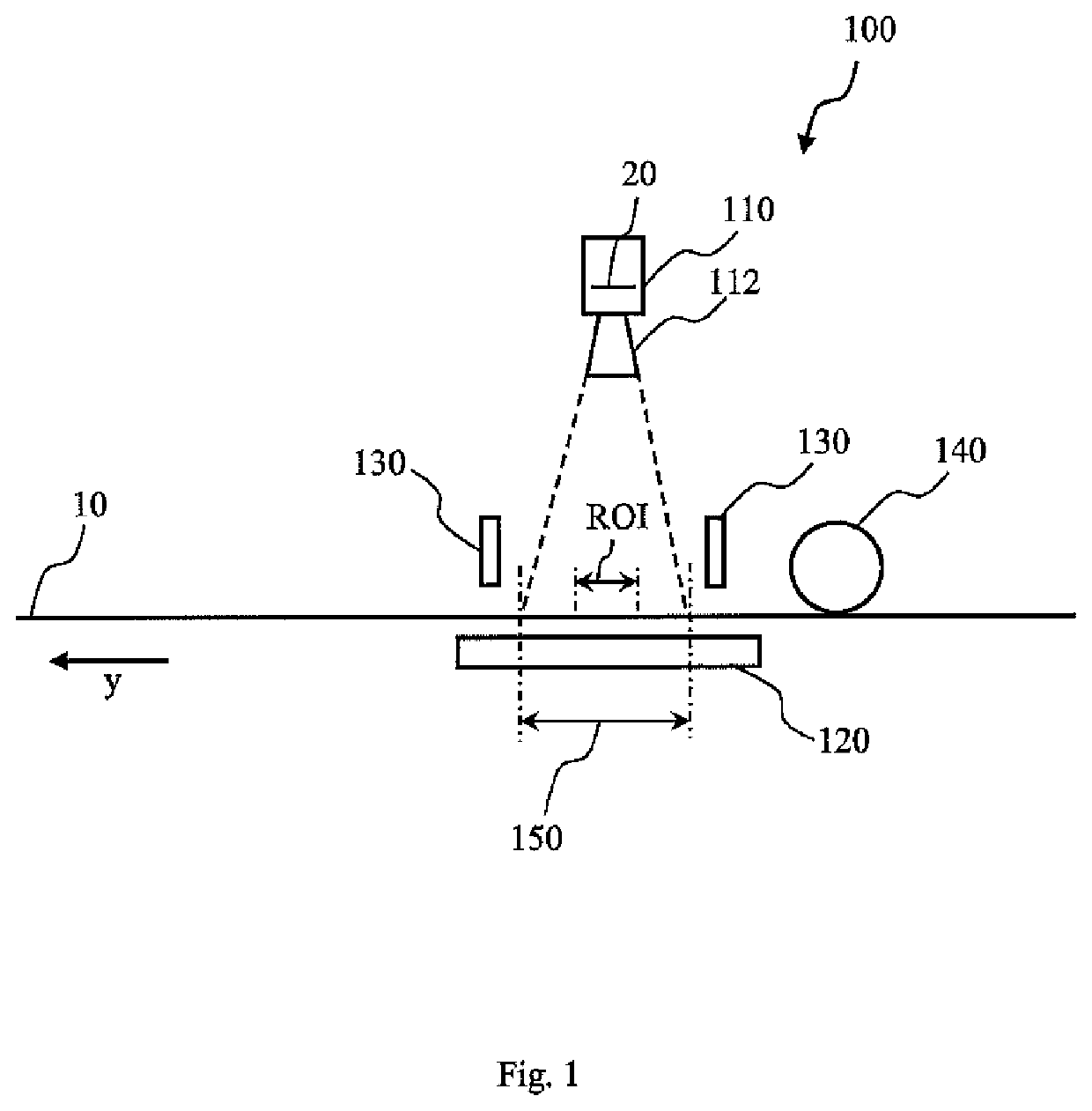
[0045]FIG. 1 is a schematic depiction of a side view of a device 100 for monitoring and / or inspecting a material web 10. The device 100 may be used for all of the methods for compensating for a material web offset described below. In addition to monitoring the web / inspection, the device may also be used to measure color density or spectral color. The device 100 comprises a...


PUM

PropertyMeasurementUnit
timeaaaaaaaaaa
timeaaaaaaaaaa
speedaaaaaaaaaa

Abstract

The invention relates to a device and a method for compensating for a material web offset in inspection systems for material webs which are moving in the direction of a material web length and / or a material web width. The method comprises the following steps: taking a first picture of a first portion of a material web at a first point in time with a camera which comprises a matrix chip, and taking a second picture of a second portion of the material web at a second point in time with the camera. A first active partial surface of the matrix chip is used for the first picture and a second active partial surface of the matrix chip is used for the second picture here, wherein the first active partial surface and the second active partial surface are not identical.

Description

FIELD OF THE INVENTION[0001]The present invention relates to a method and a device for compensating for a material web offset in monitoring and inspection systems for machines with continually transported products, such as material webs.BACKGROUND OF THE INVENTION[0002]When products are manufactured in the form of material webs, such as printed products like labels or packaging, monitoring and / or automated quality assurance after printing is of considerable importance in order to check the printed product. In addition to automated monitoring, help with visual monitoring by an operator can also be provided here. In this type of quality assurance, the material webs are passed through monitoring or inspection systems that take pictures of the material webs. These pictures can be checked by an operator or automatically. In order to guarantee that pictures are of a high quality, the material webs may be lit for the pictures using corresponding devices.[0003]In one particular type of insp...

Claims


Application Information

Patent Timeline
Patent Type & Authority Patents(United States)
IPC IPC(8): H04N7/18G01N21/88H04N5/347G01N21/89G06T7/00H04N5/225H04N5/247
CPCH04N5/2256H04N5/347G01N21/8901H04N5/247G01N21/8903G01N21/8851G06T7/0004G01N2021/8867G06T2207/30124B41F33/0036B65H23/192G01M11/00G01N21/89H04N25/46G01N21/8806G01N2021/8887H04N23/56H04N23/90
Inventor HERRMANN, MARKUSKROEHN, MANFRED
Owner TEXMAG GMBH VERTRIEBS
Learn More