
Control device for a camera apparatus, camera arrangement and method for the stereoscopic recording of a monitoring area

a control device and camera technology, applied in the field of control devices for camera equipment, camera arrangement and method for the stereoscopic recording of the monitoring area, can solve the problems of increasing image resolution and requiring computational power, and achieve the effect of reducing computational power and being easily settable by the controller

Active Publication Date: 2020-07-28
ROBERT BOSCH GMBH
View PDF4 Cites 0 Cited by
  • Summary
  • Abstract
  • Description
  • Claims
  • Application Information

AI Technical Summary

Benefits of technology

[0016]One idea of the invention is to provide a controller for a camera device in which only a small area of the recorded image is computed and / or evaluated at full resolution, without falling below a required measurement accuracy. To this end, the present invention proposes a controller in which the accuracy is ensured in the relevant image areas, but at the same time the required computational power is considerably reduced.
[0017]In one particularly preferred configuration of the invention, the control unit has an input module for inputting the limit object area and / or limit object distance. In particular, the input module is designed for the numeric, alphanumeric or graphic input of the limit object area and / or of the limit object distance. By way of example, the input module is a computer keyboard, a touchpad or a computer mouse. This configuration is based on the idea of providing a particularly easily settable controller.

Problems solved by technology

On the other hand, however, the required computational power also increases with the image resolution.

Method used


Image

  • Control device for a camera apparatus, camera arrangement and method for the stereoscopic recording of a monitoring area
  • Control device for a camera apparatus, camera arrangement and method for the stereoscopic recording of a monitoring area
  • Control device for a camera apparatus, camera arrangement and method for the stereoscopic recording of a monitoring area

Examples


Embodiment Construction

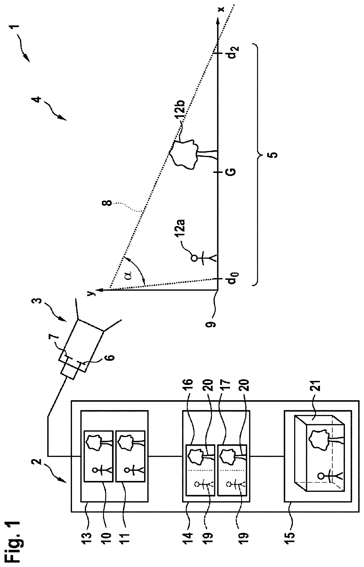
[0032]FIG. 1 schematically shows a camera arrangement 1. The camera arrangement 1 comprises a controller 2 and a camera device 3.

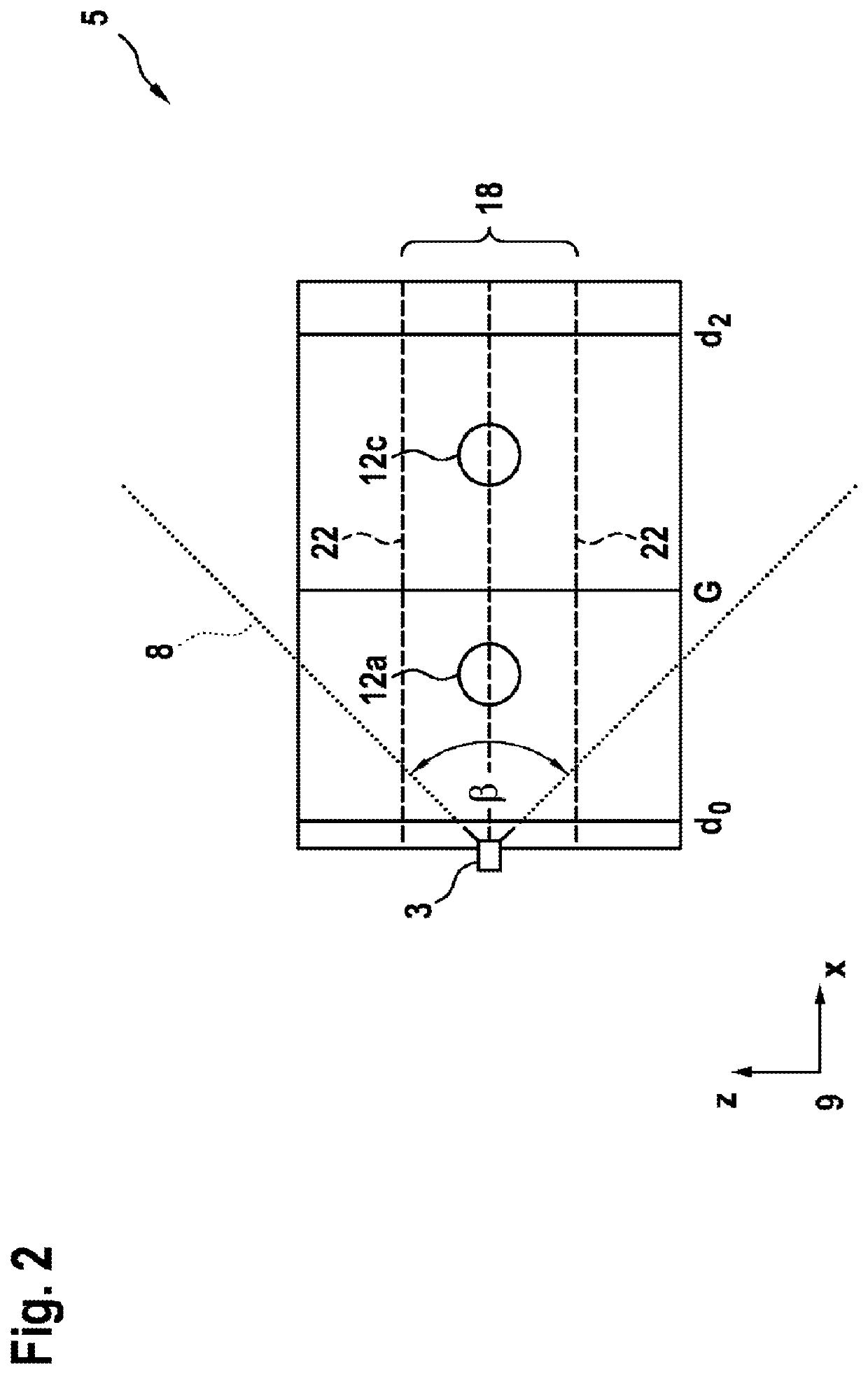
[0033]The camera device 3 is arranged in a monitoring region 4. The camera device 3 is designed to monitor a monitoring area 5, wherein the monitoring area 5 is a partial area of the monitoring region 4. The monitoring region 4 is for example an open space or an indoor area, such as for example an airport building.

[0034]The camera device 3 comprises a first camera unit 6 and a second camera unit 7. The first camera unit 6 and the second camera unit 7 are designed as imaging sensors, for example as CCD sensors or CMOS sensors. The camera device has a field of view 8, wherein the field of view 8 has an angle of aperture α in the XY plane. To this end, a coordinate system 9 is plotted by way of assistance. The Y direction of the coordinate system 9 is in particular the height direction. The angle of aperture α of the field of view 8 is in particular greater t...


PUM


Abstract

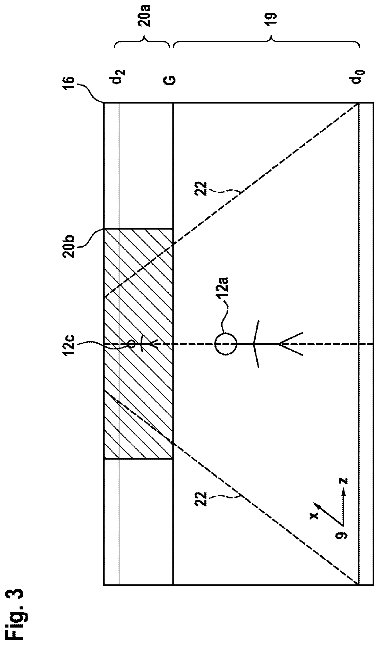
The stereoscopic recording and evaluation of a monitoring area frequently requires high computer powers. A control device (2) for a camera apparatus (3) for the stereoscopic recording of a monitoring area is proposed. In this case, recorded monitoring images (10, 11) have their resolution reduced in particular areas by a processing module and are converted into reduced images (16, 17). The reduced images have a high-resolution section (20) and a low-resolution section (19), wherein the high-resolution section (20) is a respective section showing a distant area of the monitoring area (5), the distant area being an area of the monitoring area (5) that is further away from the camera apparatus (3) than a bounding object area (G). An evaluation module (15) is used to stereoscopically evaluate the monitoring area (5) based on the first reduced image (16) and the second reduced image (17).

Description

BACKGROUND OF THE INVENTION[0001]The invention relates to a controller for a camera device for stereoscopically recording a monitoring area containing objects.[0002]Stereo cameras that allow a depth measurement are known from video monitoring technology. Such cameras are used for example to detect obstacles. In depth estimation using stereo cameras, the accuracy of the measurement on the one hand increases with the image resolution of the image-recording device that is used. On the other hand, however, the required computational power also increases with the image resolution.[0003]Document DE 10 2008 001 076 A1, which arguably forms the closest prior art, describes a method for reducing the resolution of an input image, wherein the input image shows a scene recorded by a monitoring camera. The method is characterized in that the reduction in resolution is adjusted taking into account the object distance in the scene and / or the perspective distortion of the three-dimensional scene.SU...

Claims


Application Information

Patent Timeline
Patent Type & Authority Patents(United States)
IPC IPC(8): H04N13/189H04N5/232G01B11/02H04N13/00
CPCH04N5/23206H04N13/189H04N5/23299H04N5/23222G01B11/026H04N2013/0081H04N2013/0092G06T3/0012G06T2200/24G06T2207/10012G06T2207/20096G06T2207/30196G06T2207/30232G06T7/593H04N23/64H04N23/661H04N23/695
Inventor MEYER, MICHAEL
Owner ROBERT BOSCH GMBH
Learn More