
Laser safety system

a safety system and laser technology, applied in the field of laser safety systems, can solve the problems of high intensities within the gain material, eventual catastrophic destruction of the crystal, and the risk of catastrophic failure of the disk/crystal within the high-power resonator, so as to reduce the probability of multiple disk failure, and reduce the number of laser parts

Inactive Publication Date: 2010-09-16
THE BOEING CO
View PDF8 Cites 1 Cited by
  • Summary
  • Abstract
  • Description
  • Claims
  • Application Information

AI Technical Summary

Benefits of technology

[0009]One or more embodiments of the disclosure may provide one or more of the following benefits: reduce the probability of multiple disk failures in the event of a loss of lasing within a high-power resonator; provide for the shut-down of the laser fast enough to preserve the conditions within the gain media directly following damage initiation thus enabling relatively straight forward determination of the root-cause damage mechanism; act to protect high-power system elements and offer a second level of defense against multiple failure scenarios; avoid optical component damage scenarios; allow for a significant reduction in laser parts-count through the elimination of “protector-resonators” which serve similar functions; and / or may reduce and / or eliminate other types of problems.

Problems solved by technology

High power solid state lasers often achieve high power by integrating multiple gain-modules within a common resonator thus benefiting from industrial production capability limited to lower power gain modules.
Thin disk laser gain modules may be sized by commercial laser welding needs and are typically limited to 4-5 Kw single disk designs.
Multiple-gain module scaling architectures may experience problems associated with build-up of amplified spontaneous emission (ASE) within the thin-disk gain element leading to high intensities within the gain material and eventual catastrophic destruction of the crystal.
However, if this efficient extraction is interrupted all of the disks / crystals within the high-power resonator are at risk for catastrophic failure.
These may include failure of a resonator fold mirror, failure of a single gain module, since a thin disk crystal acts as a resonator mirror, dust contaminant interrupting the beam, and other events.
Many of the existing solutions are not capable of reliably shutting down the laser within a short enough time to preserve the gain-media conditions at the time of initial damage.
However, this first line of defense can be compromised under potential loss-of-lasing scenarios.
Damage scenarios that involve initial damage to intra-cavity optical elements within the high-power resonator can create enough optical loss within the high-power resonator to create a condition of poor extraction efficiency from the thin disk by the main resonator.
However, if the initial cause of the main resonator loss of lasing also affected helper resonators they may not achieve the necessary intra-cavity intensity fast enough to prevent additional disk / crystal destruction.

Method used


Image

  • Laser safety system
  • Laser safety system
  • Laser safety system

Examples


Embodiment Construction

[0015]The following detailed description is of the best currently contemplated modes of carrying out the disclosure. The description is not to be taken in a limiting sense, but is made merely for the purpose of illustrating the general principles of the disclosure, since the scope of the disclosure is best defined by the appended claims.

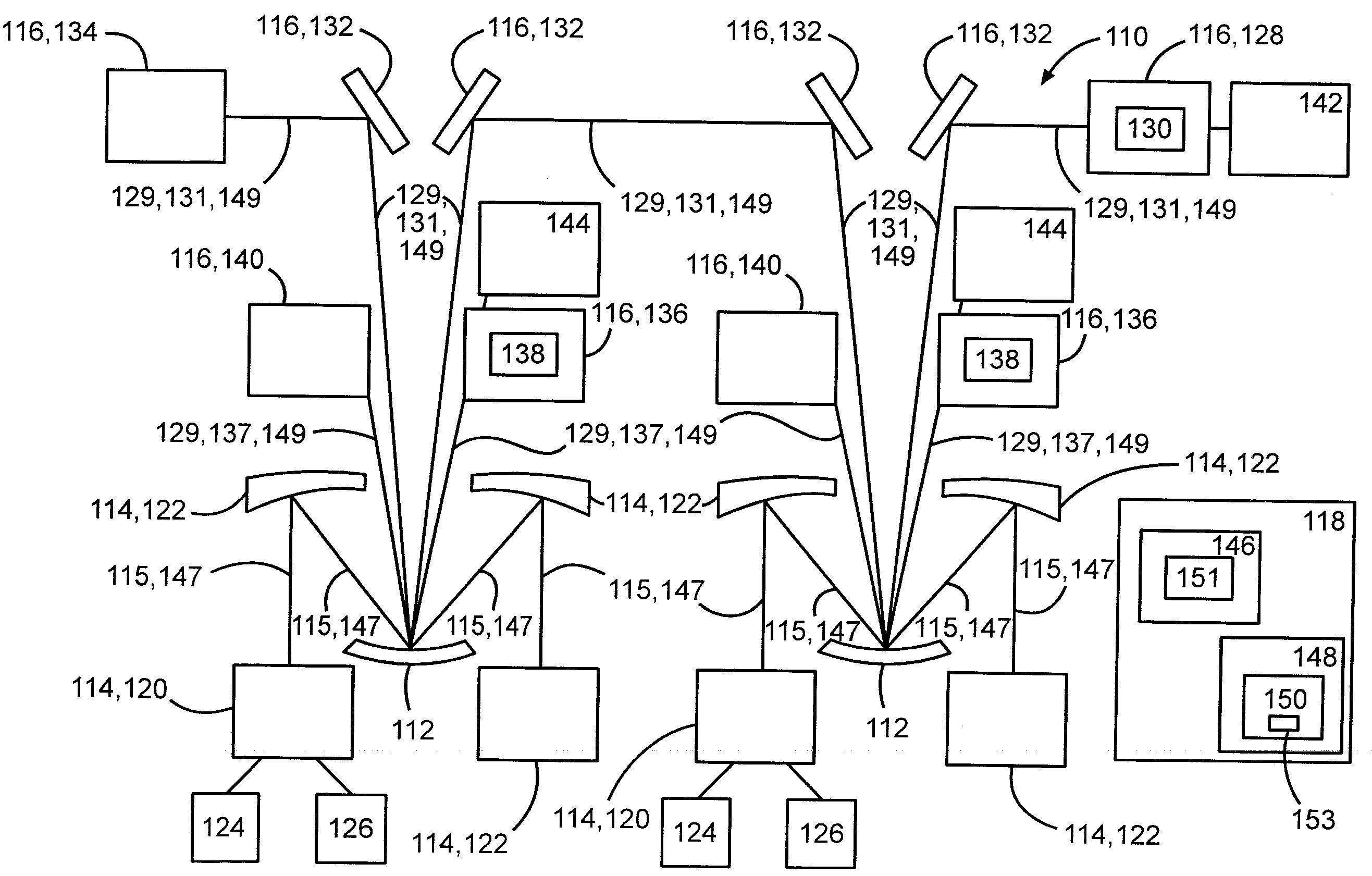
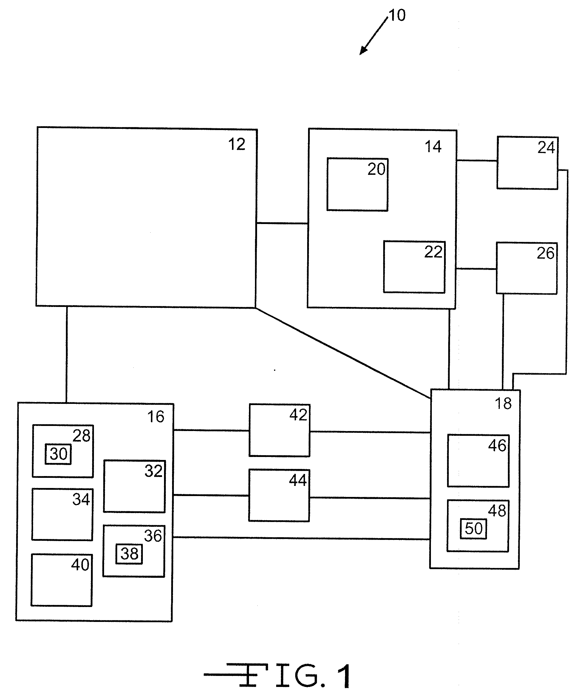
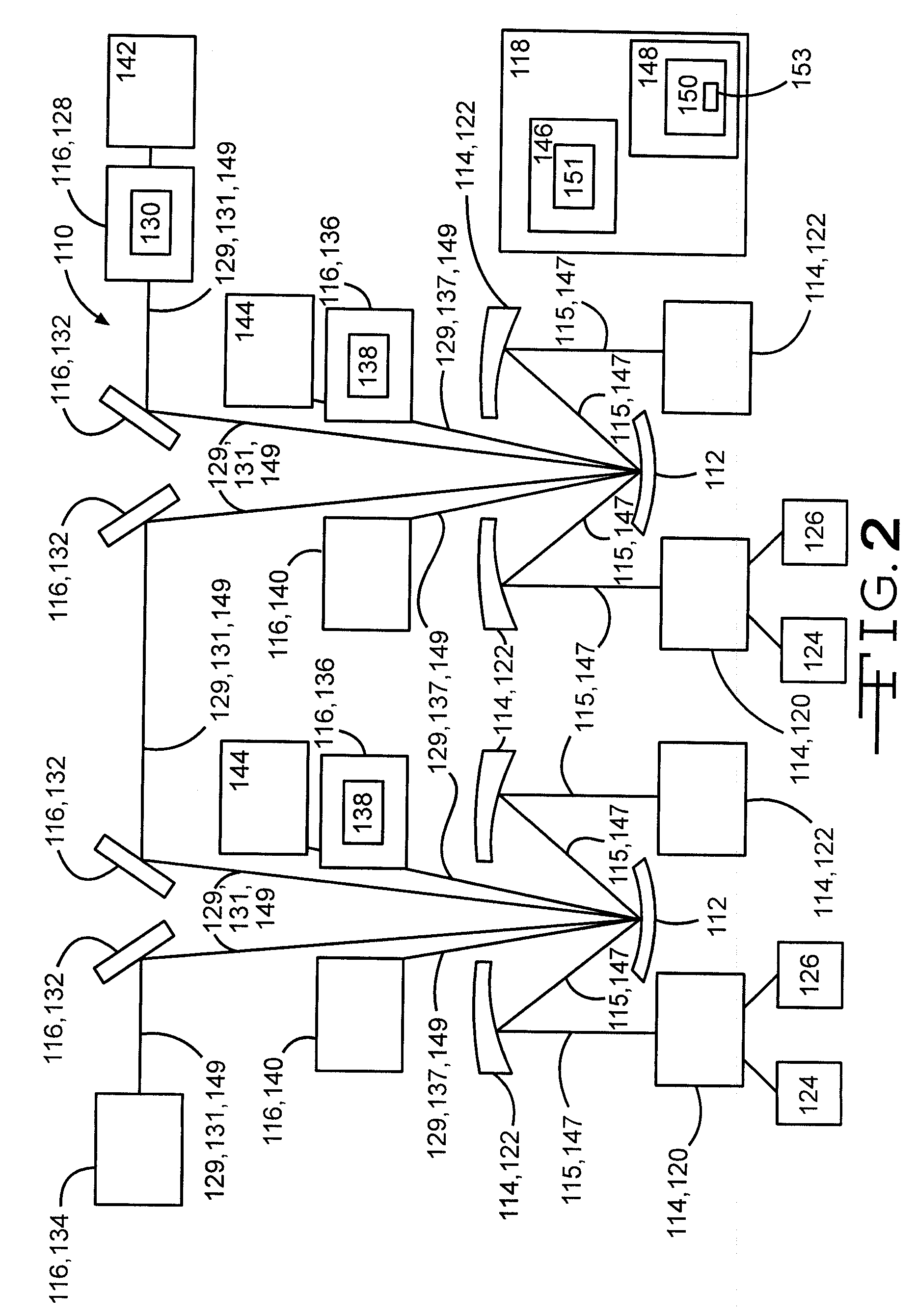
[0016]FIG. 1 illustrates a simplified box diagram of one embodiment of a laser safety system 10. The laser safety system 10 may comprise at least one gain module 12, at least one input device 14, at least one output device 16, and at least one computer 18. The at least one gain module 12 may comprise at least one thin laser disk. The at least one input device 14 may comprise one or more pump modules 20 and / or one or more pump mirrors 22. A reading device 24 and / or a detection device 26 may be in communication with the at least one input device 14. The at least one output device 16 may comprise any of a main resonator outcoupler 28, comprising a parti...


PUM

PropertyMeasurementUnit
poweraaaaaaaaaa
discharge power levelaaaaaaaaaa
discharge poweraaaaaaaaaa

Abstract

A computer may include a database and a power reducing routine. The database may be configured to store an input power level of an input laser beam transmitted onto and storing power within a gain module. The database may be further configured to store a discharge power level of at least partially discharged stored power discharged from the gain module through an output laser beam. The database may also be configured to store a power safety differential limit. The power reducing routine may include an algorithm. The algorithm may be configured to calculate a power differential by subtracting the discharge power level from the input power level, and to at least one of reduce power to and shut down the input laser beam if the calculated power differential exceeds the power safety differential limit.

Description

FIELD OF THE DISCLOSURE[0001]The field of the disclosure relates to laser safety systems.BACKGROUND OF THE DISCLOSURE[0002]High power solid state lasers often achieve high power by integrating multiple gain-modules within a common resonator thus benefiting from industrial production capability limited to lower power gain modules. Thin disk laser gain modules may be sized by commercial laser welding needs and are typically limited to 4-5 Kw single disk designs. Scaling to higher power levels is generally achieved by integrating multiple single-disk modules into a common resonator, thus achieving a power multiplier associated with the number of gain modules incorporated into the high power resonator. Multiple-gain module scaling architectures may experience problems associated with build-up of amplified spontaneous emission (ASE) within the thin-disk gain element leading to high intensities within the gain material and eventual catastrophic destruction of the crystal.[0003]The safety ...

Claims


Application Information

Patent Timeline
Patent Type & Authority Applications(United States)
IPC IPC(8): H01S3/00
CPCB23K26/426G01J1/4257G01J2001/0276H01S5/06825H01S3/1312H01S5/041H01S3/1305B23K26/705
Inventor CURTIN, MARK S.WIDEN, KENNETH C.
Owner THE BOEING CO
Learn More