
Lens Systems And Method

a technology of lenses and lenses, applied in the field of lenses, can solve the problems of affecting the use of lenses other devices where space is at a premium, and the potential for miniaturization of such lenses for use in cell phones, medical endoscopes, etc., and achieves the effect of improving the use efficiency and reducing the cost of lens components

Active Publication Date: 2010-09-16
OPTOTUNE CONSUMER AG
View PDF99 Cites 75 Cited by
  • Summary
  • Abstract
  • Description
  • Claims
  • Application Information

AI Technical Summary

Benefits of technology

The patent text describes a new type of zoom lens system that overcomes the limitations of conventional zoom lenses and previous approaches. The system uses deformable lenses that can be tuned using various actuators, and operates on the principle of varifocal optics. The system is compact and can provide a high zoom factor with a wide range of focus adjustment. The technical effects of this new system include improved image quality, reduced space consumption, and improved user satisfaction.

Problems solved by technology

Using either approach, conventional zoom lenses are space consuming, expensive and prone to material wear as several optical elements have to be axially shifted relative to the others by means of motorized translation stages.
The potential for miniaturization of such lenses for use in cell phones, medical endoscopes, or other devices where space is at a premium is limited due to their functional principles and operation.
Unfortunately, these previous approaches still suffered from several disadvantages.
More specifically, their potential to sufficiently reduce axial length while providing a high zoom factor and sufficient image size on the image sensor was still limited either due to the chosen zoom principle (e.g., afocal / parfocal systems) or due to the composition or operating principles of the deformable lenses that did not offer sufficient tuning range (e.g., electrowetting lenses or liquid crystal lenses).
Consequently, the disadvantages present in these previous systems limited their application and created user dissatisfaction with these previous approaches.

Method used


Image

  • Lens Systems And Method
  • Lens Systems And Method
  • Lens Systems And Method

Examples


Embodiment Construction

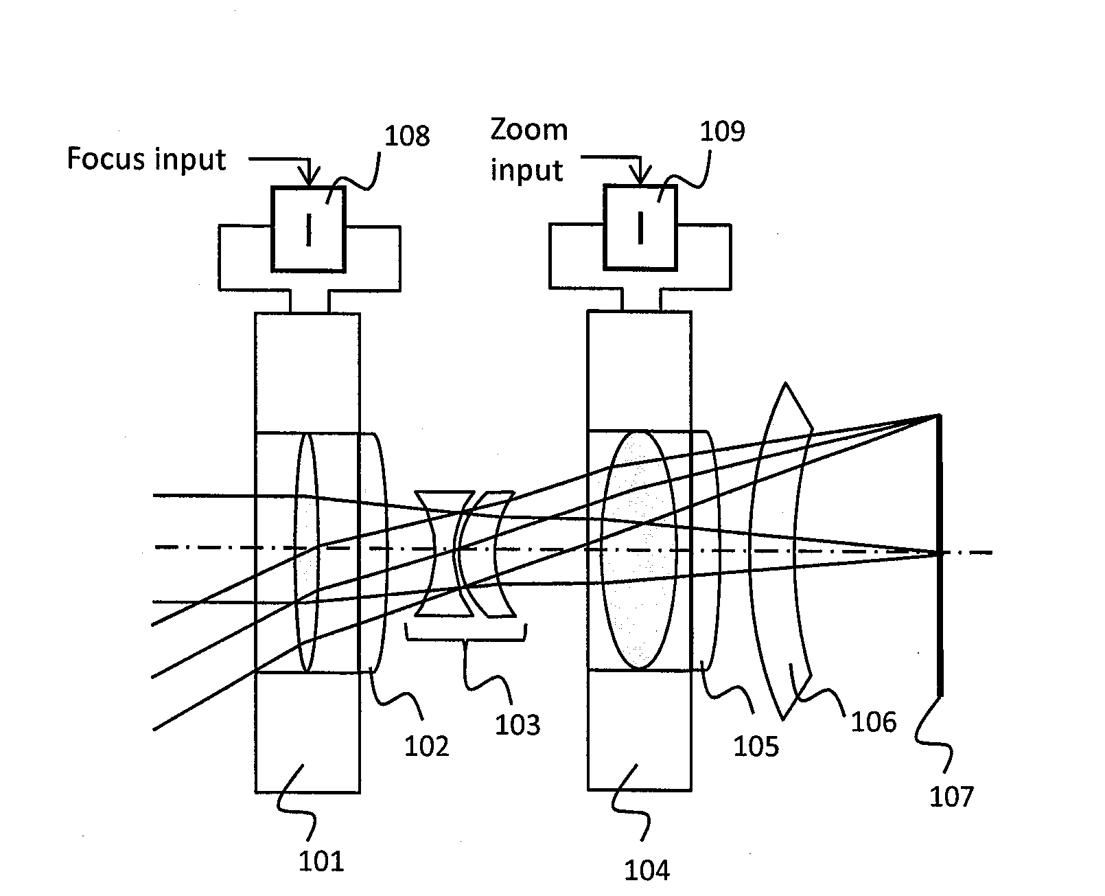
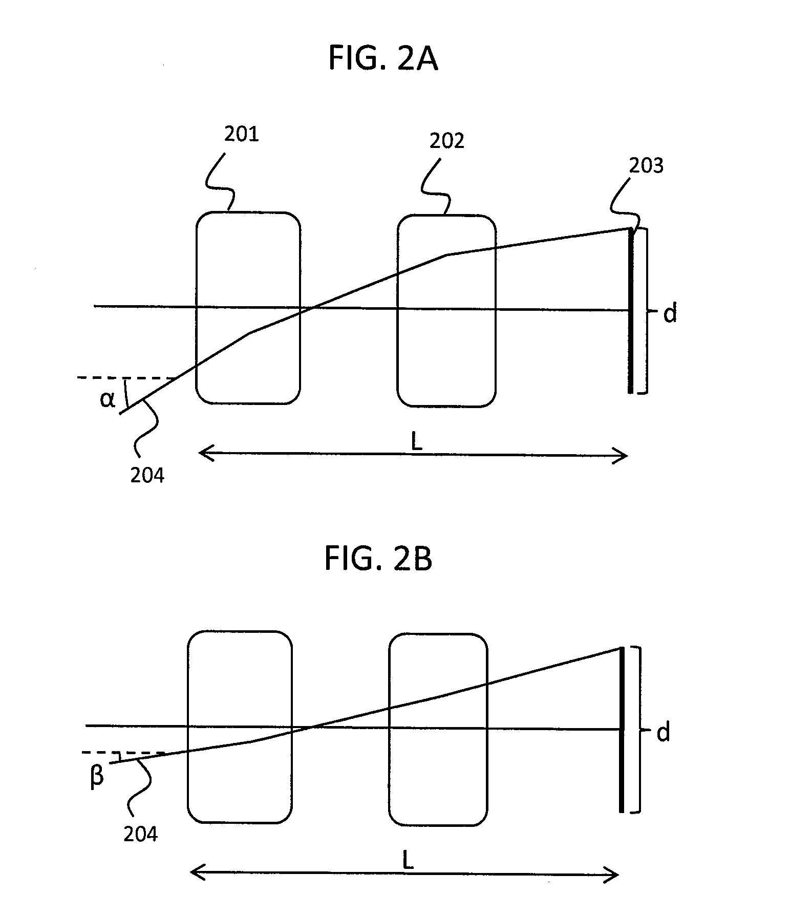
[0019]Zoom lenses are provided with deformable lenses that overcome the disadvantages of both conventional zoom lenses and previous approaches that utilized deformable lenses. The deformable lenses provided herein are, to give a few examples, tuned at least in part by an element such as an electrostatic actuator, an electromagnetic actuator, a piezo motor, a magneto-strictive actuator, a stepper motor, or an electroactive polymer actuator offering a high focus tuning range. Additionally, the zoom lenses presented herein utilize varifocal operating principles instead of the afocal / parfocal principles. In one example of the present approaches, a single focus tunable lens is used as a single autofocus element.

[0020]In many of these embodiments, a compact zoom lens includes a first deformable lens that is constructed of a membrane with a deformable portion and a filler material. In these approaches, deformation is achieved at least in part by an element such as an electrostatic actuator...


PUM


Abstract

An optical system includes a first deformable lens having a membrane with a deformable portion. A sensor is configured to receive the light focused by the first deformable lens. An optical path extends through the first deformable lens and to the sensor. The first deformable lens is tuned according to an applied electrical signal in order to directly focus light traversing the optical path onto the sensor. A first volume of a first optical media and a second volume of a second optical media are defined at least in part by the deformable portion of the membrane. The first volume and the second volume are completely enclosed by the housing. The first volume and the second volume remain substantially constant for all configurations of the first deformable lens.

Description

CROSS REFERENCES TO RELATED APPLICATIONS[0001]This patent claims benefit under 35 U.S.C. §119 (e) to U.S. Provisional Application No. 61 / 160,012 entitled “Zoom Lens System and Method” filed Mar. 13, 2009 having attorney docket No. P09006 the contents of which are incorporated herein by reference in their entirety.TECHNICAL FIELD[0002]This patent relates to lenses and methods of operating lenses.BACKGROUND OF THE INVENTION[0003]Various types of optical systems that utilize different operational principles exist. For instance, an afocal lens has no focusing power and transfers parallel light rays of one beam diameter to parallel light rays of another diameter. By adding a single focusing lens after the afocal system, a parfocal lens is created. In a conventional zoom lens system, only the lens elements of the afocal portion have to be moved forth and back to obtain the zoom effect, while the focusing lens can remain static. Consequently, a parfocal lens stays in focus when magnificati...

Claims


Application Information

Patent Timeline
Patent Type & Authority Applications(United States)
IPC IPC(8): H04N5/232G02B7/04
CPCG02B3/14G02B27/0025G02B7/04H04N5/23212H04N5/2254G02B3/0081G02B27/005
Inventor BUELER, MICHAELASCHWANDEN, MANUELGRATZEL, CHAUNCEYNIEDERER, DAVID
Owner OPTOTUNE CONSUMER AG
Learn More