
Voice mixing device, noise suppression method and program therefor

a voice mixing and noise suppression technology, applied in the field of voice mixing devices, can solve the problems of abnormal sound generation, background noise often superimposed on voice signals, etc., and achieve the effect of reducing abnormal sound generation

Active Publication Date: 2010-09-09
RAKUTEN GRP INC
View PDF4 Cites 12 Cited by
  • Summary
  • Abstract
  • Description
  • Claims
  • Application Information

AI Technical Summary

Benefits of technology

[0010]Since conventional multipoint conferencing is configured such that noise suppression processing is performed on speech of all participants, computation amount with regard to noise suppression processing may increase along with increasing participants. As a method for solving this, a method can be conceived in which a speaker who makes an utterance is detected, and by mixing only a voice signal of the detected speaker, the number of noise suppression processes that are activated is reduced.
[0012]It is an object of the present invention to provide a voice mixing device, a noise suppression method and program therefor, which will eliminate the problem.
[0029]According to the present invention, when noise suppression unit is switched along with switching of a speaker, since information of noise suppression after switching is the same as information of noise suppression before switching, it is possible to reduce generation of abnormal sound.

Problems solved by technology

However, in the multipoint conference service, particularly in cases in which participants are using mobile telephones, background noise is often superimposed on the voice signals.
In a multipoint conference service, particularly in cases in which participants are using mobile terminals, background noise is often superimposed on voice signals.
However, when noise suppression processing is applied to this method, a nonconformity occurs among past noise suppression information retained in the noise suppression processing, so that there is a risk of an abnormal sound being generated, counted as a problem.

Method used


Image

  • Voice mixing device, noise suppression method and program therefor
  • Voice mixing device, noise suppression method and program therefor
  • Voice mixing device, noise suppression method and program therefor

Examples


first exemplary embodiment

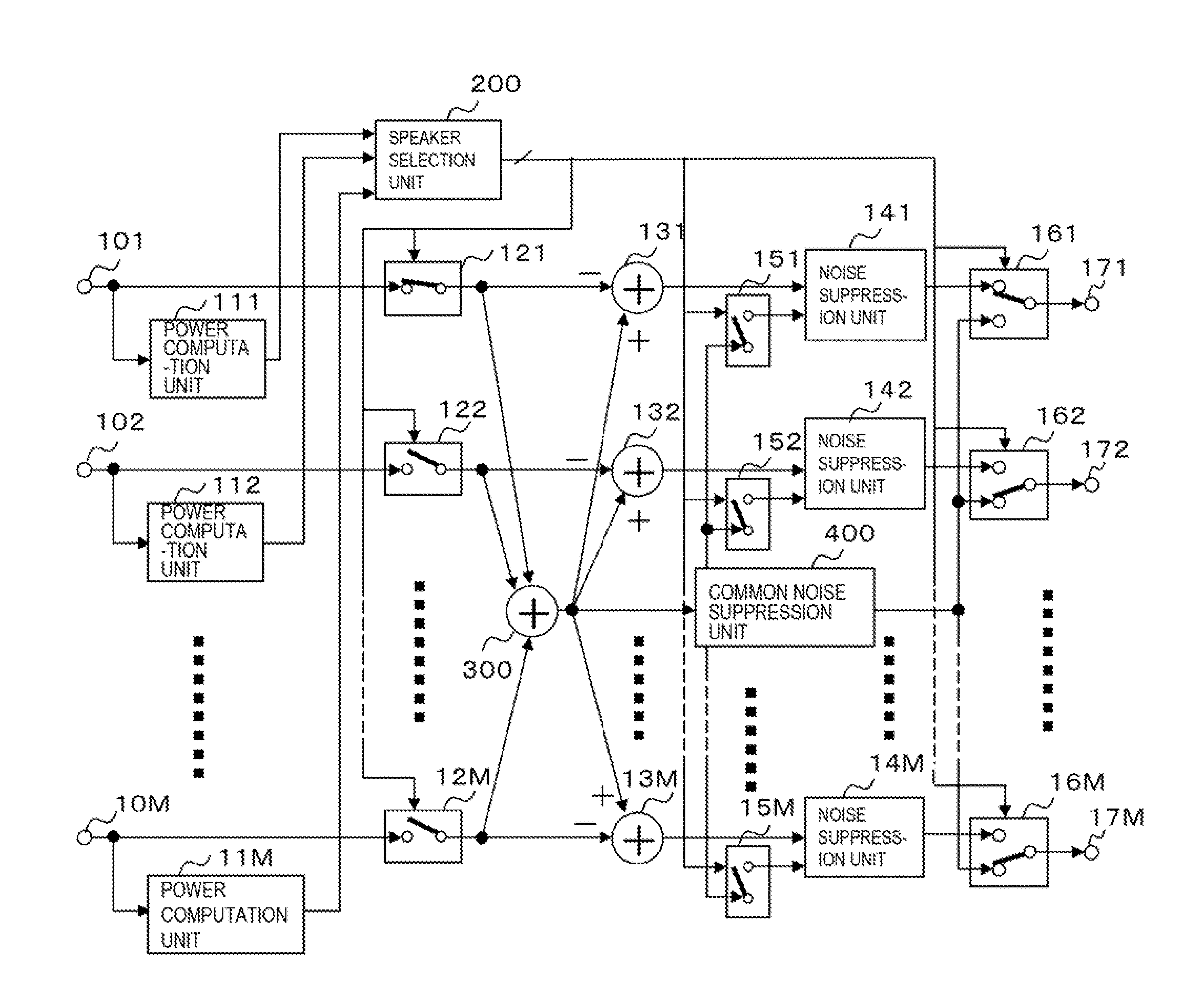
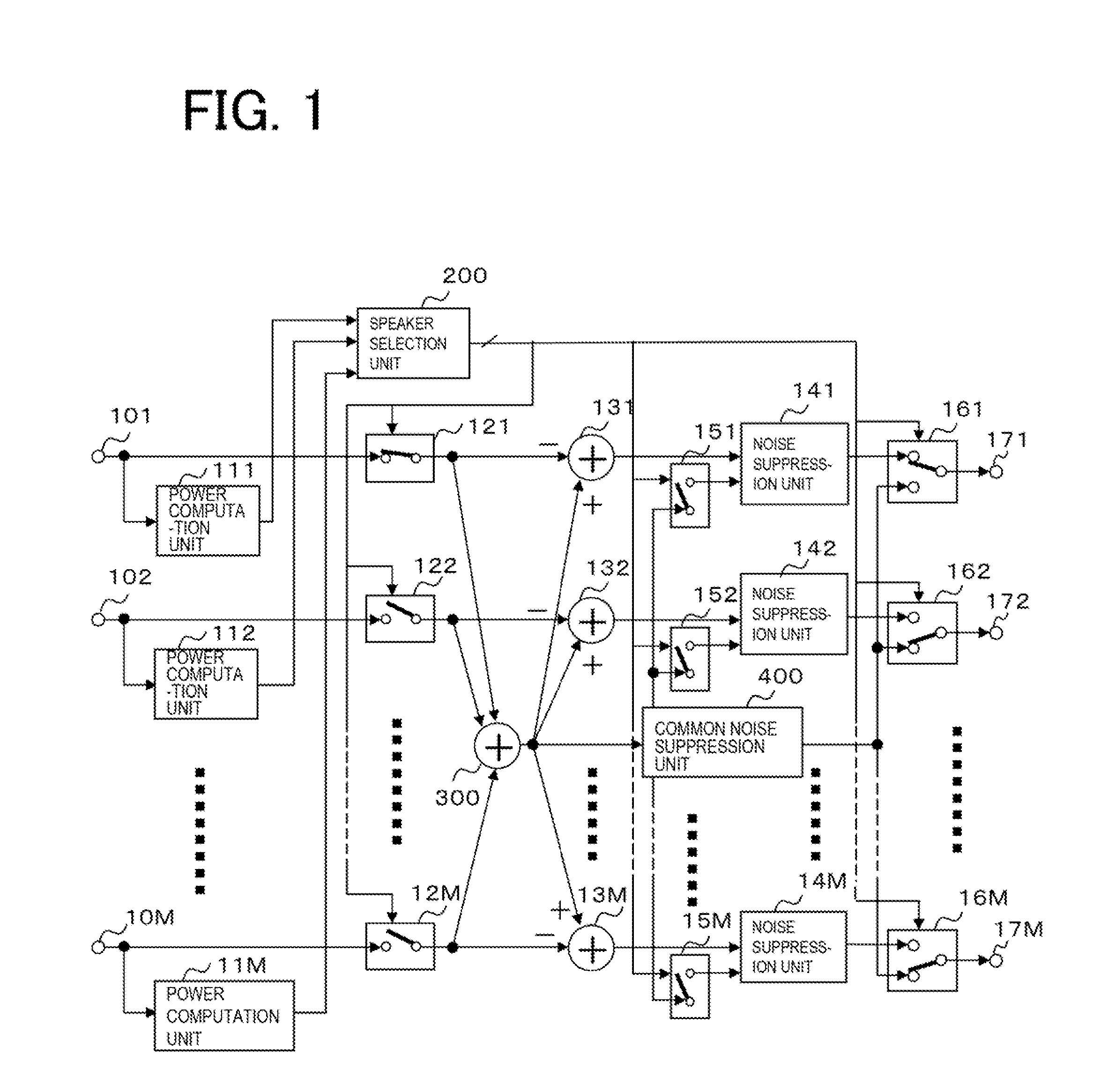
[0051]FIG. 1 is a block diagram showing a configuration of a voice mixing device according to a first exemplary embodiment of the present invention (translation note: the term “voice” herein represents “speech voice” or “speech”). In FIG. 1, a multipoint conference system is provided with voice input terminals 101, 102, . . . 10M, power computation units 111, 112, . . . 11M, a speaker selection unit 200, voice signal input switching units 121, 122, . . . 12M, a full (all) signal adder 300, adders 131, 132, . . . 13M, a common noise suppression unit 400, noise suppression units (individual noise suppression units) 141, 142, . . . 14M, memory switching units 151, 152, . . . 15M, voice data switching units 161, 162, . . . 16M, and voice output terminals 171, 172, . . . 17M.

[0052]The power computation units 111, 112, . . . 11M compute power of voice signals inputted from the voice input terminals 101, 102, . . . 10M respectively corresponding to speaker 1, speaker 2, . . . and speaker M...

second exemplary embodiment

[0075]FIG. 3 is a block diagram showing a configuration of a voice mixing device according to a second exemplary embodiment of the present invention. In FIG. 3, noise suppression switching units 181, 182, . . . 18M, and noise suppression units (preliminary noise suppression units) 191, 192, . . . 19M are added to the voice mixing device of FIG. 1. Below, in order to simplify the description, only differences from the first exemplary embodiment will be described.

[0076]The noise suppression units 181, 182, . . . 18M perform switching as to whether to output voice signals inputted from respective voice input terminals 101, 102, . . . 10M to the respective noise suppression units 191, 192, . . . 19M, or to respective power computation units 111, 112, . . . 11M, and voice signal input switching units 121, 122, . . . 12M. In cases in which a terminal used by a participant is a mobile telephone, for example, since background noise is considered to be superimposed, by an input signal being ...


PUM


Abstract

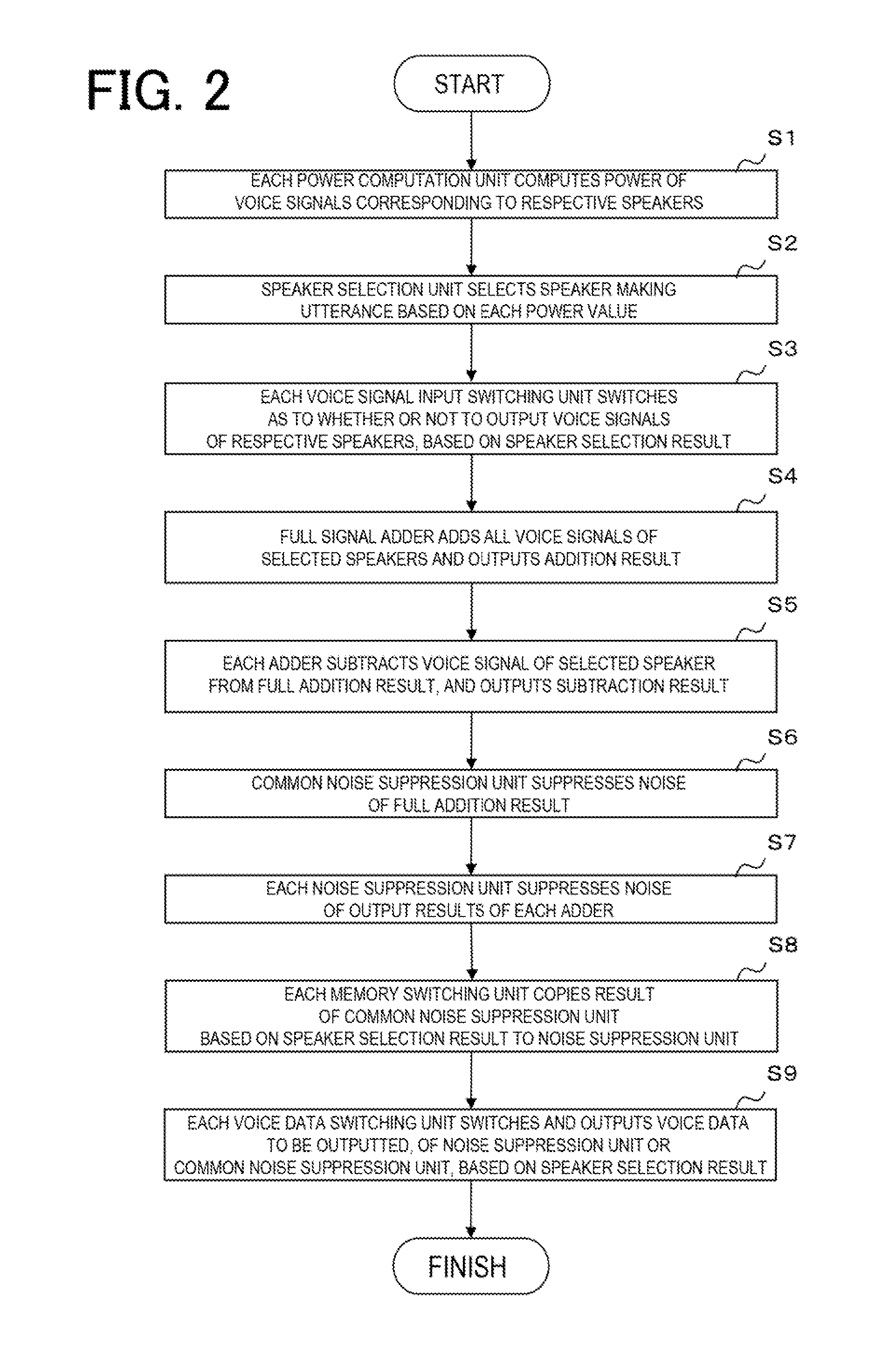
A voice mixing device for mixing a plurality of voice signals, comprises: a speaker selection unit selecting at least one voice signal among said plurality of voice signals; a full signal adder unit adding all of at least one voice signal selected by said speaker selection unit; respective subtractor unit subtracting only one of said selected voice signals from an addition result of said full signal adder unit; a common noise suppression unit suppressing noise of a common voice signal, being an addition result of said full signal adder unit; individual noise suppression unit suppressing noise of respective individual voice signals, being subtraction results of said subtractor unit; and memory switching unit copying information of noise suppression obtained in said common noise suppression unit based on a selection result of said speaker selection unit, to information of noise suppression in said individual noise suppression unit.

Description

REFERENCE TO RELATED APPLICATION[0001]This application is the National Phase of PCT / JP2008 / 063507, filed Jul. 28, 2008, which is based upon and claims the benefit of the priority of Japanese patent application No. 2007-205443, filed on Aug. 7, 2007, the disclosure of which is incorporated herein in its entirety by reference thereto.TECHNICAL FIELD[0002]This invention relates to a voice mixing device, a noise suppression method and program therefor, and in particular, to technology for suppressing noise superimposed on voice in a multipoint conference.BACKGROUND ART[0003]In a multipoint conference service, voice data of each participant is transmitted to a multipoint conference server. The multipoint conference server transmits to each participant a voice signal that is a mixed voice signal of all other participants. FIG. 4 is a drawing showing a typical configuration example with regard to a voice mixing device for a multipoint conference (refer to Patent Documents 1 and 2). In FIG....

Claims


Application Information

Patent Timeline
Patent Type & Authority Applications(United States)
IPC IPC(8): G10L21/02G10L21/0208G10L21/0224
CPCH04M3/56G10L21/0208
Inventor ITO, HIRONORIOZAWA, KAZUNORI
Owner RAKUTEN GRP INC
Learn More