Projection optical system, exposure apparatus, and device manufacturing method

Active Publication Date: 2010-09-09
CANON KK
View PDF1 Cites 18 Cited by
  • Summary
  • Abstract
  • Description
  • Claims
  • Application Information

AI Technical Summary

Benefits of technology

[0007]A projection optical system according to one aspect of the present invention is configured to project an image of an object plane onto an image plane, and includes a first optical element having an aspheric surface that is rotationally asymmetric with respect to an optical axis, a moving unit configured to move the first optical el

Problems solved by technology

However, in JP 10-242048, the fine gap between the pair of optical elements causes an aberration.
For example, the gap of 100 μm between the pair of optical elements causes non-negligible amounts of distortion and astigmatism but it is difficult to further reduce the gap between them.
In other words, the conventional exposure apparatus using the pair of optical elements causes an aberration and deteriorates the overlay accuracy.

Method used


Image

  • Projection optical system, exposure apparatus, and device manufacturing method
  • Projection optical system, exposure apparatus, and device manufacturing method
  • Projection optical system, exposure apparatus, and device manufacturing method

Examples


first embodiment

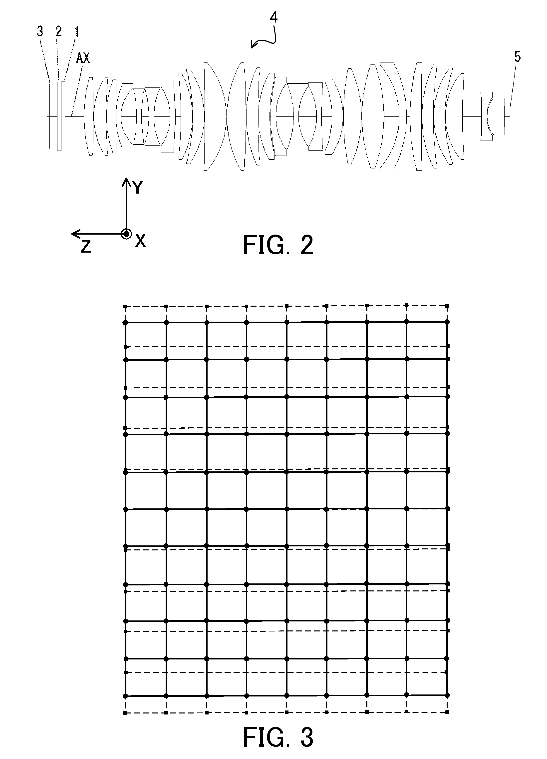
[0042]FIG. 2 is a sectional view of a specific structure (first embodiment) of a plurality of optical elements included in the projection optical system 4. The projection optical system 4 of the first embodiment is used for a light source of a KrF excimer laser having a wavelength of 248 nm, and has a NA of 0.65 and a projection magnification of −¼ times. The substrate 5 has a rectangular exposure area of 26×33 mm. Table A shows an effective diameter, a radius of curvature, a surface separation (surface distance), and a glass type of each surface of the projection optical system 4.

TABLE ASurfaceEffectiveRadius ofSurfaceGlassNumberDiameterCurvatureSeparationType1168.4∞20.0002175.1∞10.000SiO23XY177.3∞0.1004XY177.3∞10.000SiO25179.6∞49.9006201.1360.3559524.239SiO27201.2−2626.126451.0008ASP200.9194.6904831.899SiO29197.61033.394231.00010190.2263.7673824.000SiO211185.32469.143711.00012169.8213.7500113.000SiO213145.8100.9976940.81614145.0−345.0748713.000SiO215141.6380.6135019.07216141.6−245...

second embodiment

[0061]FIG. 8 is a sectional view of a specific structure (second embodiment) of a plurality of optical elements included in the projection optical system 4. This embodiment provides two correction members 21 and 22. The projection optical system 4 of the second embodiment is used for a light source of a KrF excimer laser having a wavelength of 248 nm, and has a NA of 0.60 and a projection magnification of −¼ times. The substrate 5 has a rectangular exposure area of 26×33 mm. Table B shows an effective diameter, a radius of curvature, a surface separation, and a glass type of each surface of the projection optical system 4.

TABLE BSurfaceEffectiveRadius ofSurfaceGlassNumberDiameterCurvatureSeparationType1168.4∞20.0002XY174.6∞8.000SiO23176.2∞51.9004192.3∞10.000SiO25XY194.3∞0.1006XY194.3∞24.000SiO27196.1−317.743751.0008ASP195.0128.8237347.208SiO29189.91321.211731.00010172.0180.9301613.000SiO211146.995.5345539.68912146.1−823.6396913.000SiO213138.2126.9235942.56014138.9−129.8763013.000SiO...


PUM


Abstract

A projection optical system is configured to project an image of an object plane onto an image plane, and includes a first optical element having an aspheric shape that is rotationally asymmetric with respect to an optical axis, a moving unit configured to move the first optical element in a direction perpendicular to the optical axis, and a second optical element fixed on the optical axis, and configured to reduce an optical path length difference caused by an aspheric surface of the first optical element, the second optical element having no aspheric shape complement to the aspheric shape of the first optical element.

Description

BACKGROUND OF THE INVENTION[0001]1. Field of the Invention[0002]The present invention relates to a projection optical system, an exposure apparatus, and a device manufacturing method.[0003]2. Description of the Related Art[0004]Japanese Patent Application No. (“JP”) 10-242048 proposes a method for controlling an aberration of a projection optical system in an exposure apparatus by shifting each of a pair of optical elements (in an Alvarez lens) in a direction perpendicular to an optical axis, where the pair of optical elements have complement aspheric surfaces facing each other and are separated by a fine gap in the Alvarez lens.[0005]However, in JP 10-242048, the fine gap between the pair of optical elements causes an aberration. For example, the gap of 100 μm between the pair of optical elements causes non-negligible amounts of distortion and astigmatism but it is difficult to further reduce the gap between them. In other words, the conventional exposure apparatus using the pair o...

Claims


Application Information

Patent Timeline
IPC IPC(8): G03F7/207G02B13/18G03B27/52
CPCG02B13/143G02B13/18G03F7/70308G03B27/52G02B27/0068
Inventor SUMIYOSHI, YUHEI
Owner CANON KK
Why Eureka
Try Eureka