
Stator cooling structure for superconducting rotating machine

a superconducting rotating machine and cooling structure technology, which is applied in the direction of mechanical energy handling, magnetic circuit rotating parts, shape/form/construction, etc., can solve the problems of increasing the distortion factor of the waveform of generated voltage, difficult to obtain a desired output power, and complicated cooling device using water/oil cooling method, etc., to achieve compact machine, reduce the clogging of cooling tubes, and reduce the effect of clogging

Inactive Publication Date: 2010-09-09
DOOSAN HEAVY IND & CONSTR CO LTD
View PDF6 Cites 15 Cited by
  • Summary
  • Abstract
  • Description
  • Claims
  • Application Information

AI Technical Summary

Benefits of technology

[0019]As described above, the present invention is advantageous in that a cooling tube simultaneously contacts both a stator coil and a stator yoke, thus simultaneously cooling the stator yoke as well as the stator coil.
[0020]Further, the cooling tube is not disposed in a stator slot, thus preventing the cooling tube from becoming clogged at the bent portion of the tube. It is not necessary to connect several cooling tubes to each other, thus reducing the clogging of the cooling tubes which may occur when they are welded to each other. A worker has only to spirally wind the cooling tube outside the stator coil, so that the manufacture of a stator cooling structure is very simple, a compact machine is achieved, and the ratio of the stator coil to be occupied in the slot can be increased. Flux linkage between the cooling tube and a rotor is very small, thus considerably reducing eddy current which may be generated in the cooling tube.

Problems solved by technology

However, the air cooling method using natural convection never requires an additional cooling device, and the air cooling method using forced convection requires the installation of only a cooling fan (blower).
But, a cooling device using the water / oil cooling method becomes very complicated.
Since a conventional rotating machine uses coils made of copper, it is difficult to obtain a desired output power unless the core is used, and an air gap between a stator core and a rotor core is very small so as to maximize flux linkage between stator coils and rotor coils.
Further, the slots are different in permeability from the coils, thus causing the increase in the distortion factor of the waveform of generated voltage.
However, since the heat conductivity of FRP is a lot smaller than that of the core, heat generated in the stator coils is not easily dissipated.
Thus, the cooling tubes 8 are apt to become narrow or clogged, and it is very difficult to manufacture.
Further, since the cooling tubes 8 are disposed in spaces in the stator slots which are to be occupied by conductors, the ratio of the stator conductors occupied in the slots is reduced, thus causing an increase in the size of the machine.
Thus, unless a slot for supporting the stator coils 9 is used as shown in FIG. 5, a machine may be broken or damaged.
Hence, when the stator coils 9 are burn out, it is difficult to repair just them in isolation.
The multiple phase coils overlap each other, so that electric insulation may easily deteriorate.
However, the cooling structure is unsuitable for a low-speed and high-torque industrial vessel propelling motor or wind turbine, in which a very large electromagnetic force acts on the stator coils.
Thus, in order to ensure a flux linkage for a desired output power, a larger amount of expensive superconducting wires is required in filed coils, so that manufacturing costs are undesirably increased.

Method used


Image

  • Stator cooling structure for superconducting rotating machine
  • Stator cooling structure for superconducting rotating machine
  • Stator cooling structure for superconducting rotating machine

Examples


Embodiment Construction

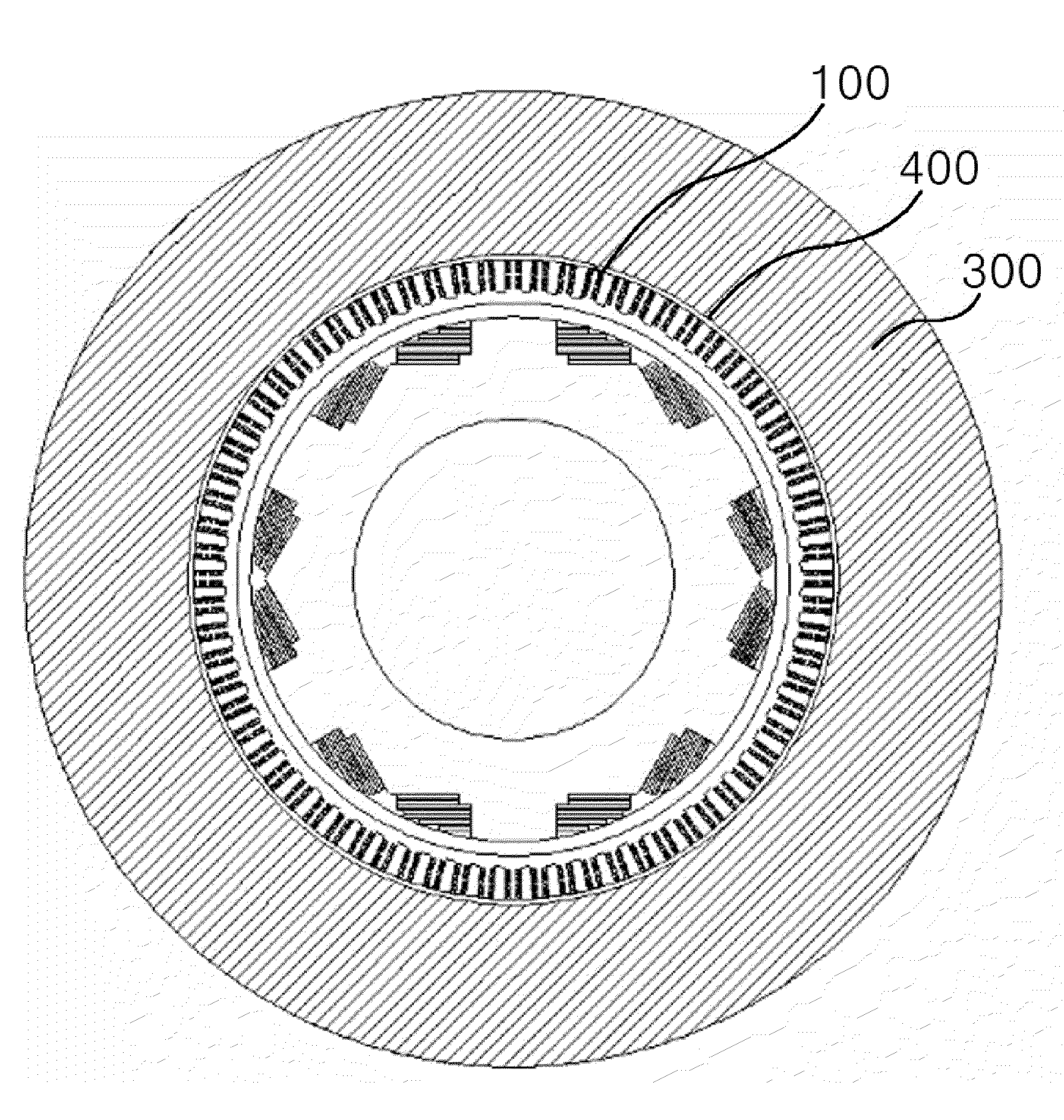
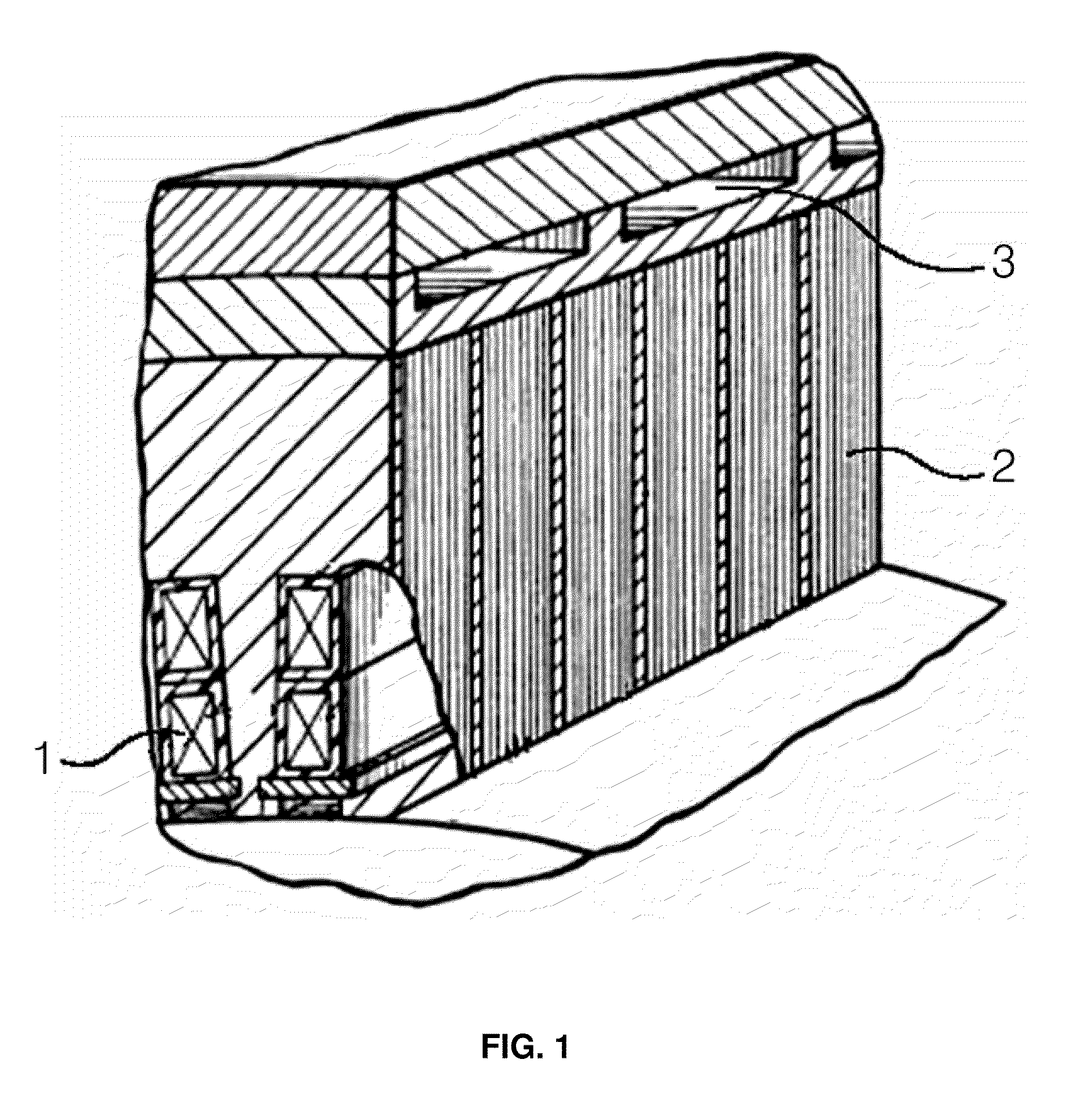
[0030]The present invention is directed to a cooling structure for efficiently eliminating heat generated from the stator coil of a superconducting rotating machine, that is, a superconducting motor or generator. Instead of arranging water / oil cooling tubes in slots, cooling tubes are spirally placed between the outside portion of a stator coil and a stator yoke, so that non-magnetic slots are maintained to withstand electromagnetic force acting on the stator coil. Further, spaces are provided axially between the slots, so that the spiral cooling tubes are disposed in the spaces. Thereby, the stator cooling structure for the superconducting rotating machine is capable of cooling the stator yoke as well as the stator coil.

[0031]Hereinafter, the preferred embodiment of the present invention will be described in detail with reference to the accompanying drawings. FIGS. 6 and 7 are a transverse sectional view and a vertical sectional view, respectively, illustrating the stator cooling s...


PUM


Abstract

Disclosed herein is a structure for cooling the stator of a superconducting rotating machine. The structure includes a stator coil. Slots are axially disposed at the stator coil to support the stator coil, and a space is defined between the slots to allow the stator coil to be partially exposed. A stator yoke is disposed on the slots such that a space is defined between the exposed portion of the stator coil, the slots and the stator yoke. A cooling tube is disposed in the space defined between the exposed portion of the stator coil, the slots and the stator yoke, thus simultaneously cooling both the stator coil and the stator yoke.

Description

FIELD OF THE INVENTION[0001]The present invention relates generally to a structure for cooling the stator of a superconducting rotating machine, that is, a superconducting motor or generator and, more particularly, to a stator cooling structure for a superconducting rotating machine, in which a stator coil is exposed to a cooling tube received in a space between slots and a stator yoke is disposed on the cooling tube, so as to directly cool both the stator coil and the stator yoke through the cooling tube.BACKGROUND OF THE INVENTION[0002]The stators of most conventional motors are cooled through the natural convection or forced convection of air. Some stators may be cooled using water or oil. The density of an electric current which may flow in a stator coil in the case of using the air cooling method is relatively lower than that of an electric current in the case of using the water or oil cooling method. However, the air cooling method using natural convection never requires an ad...

Claims


Application Information

Patent Timeline
IPC IPC(8): H02K9/00
CPCH02K1/20H02K3/24H02K7/1823H02K7/1838H02K55/04Y02E40/625H02K7/183Y02E40/60H02K1/32H02K9/16
Inventor BAIK, SEUNG- KYUKWON, YOUNG-KILKIM, HO-MIN
Owner DOOSAN HEAVY IND & CONSTR CO LTD
Learn More