Eureka AIR delivers breakthrough ideas for toughest innovation challenges, trusted by R&D personnel around the world.

Ultrasonic humidifier for repelling insects

a humidifier and ultrasonic technology, applied in the field of ultrasonic humidifiers, can solve problems such as reducing efficiency, and achieve the effect of reducing efficiency

Inactive Publication Date: 2010-09-09
MONSTER MOSQUITO SYST
View PDF108 Cites 37 Cited by
  • Summary
  • Abstract
  • Description
  • Claims
  • Application Information

AI Technical Summary

Benefits of technology

[0009]The present invention is directed to an ultrasonic repellent humidifier for dispersing insect repellant into the air as a micro fine repellent vapor. A repellent tank provides rhodinol and cedarwood oil based repellent to a repellent well. An ultrasonic transducer is positioned in the well beneath the level of the repellent. It vibrates, forming a repellant vapor that is drawn into a vapor duct by a forced air system a...

Problems solved by technology

The vibrating portion of the ultrasonic transducer that is exposed to the oil-based repellent is a ceramic material that inhibits residue from forming on the transducer that reduces its efficiency.

Method used


Image

  • Ultrasonic humidifier for repelling insects
  • Ultrasonic humidifier for repelling insects
  • Ultrasonic humidifier for repelling insects

Examples


Embodiment Construction

[0031]

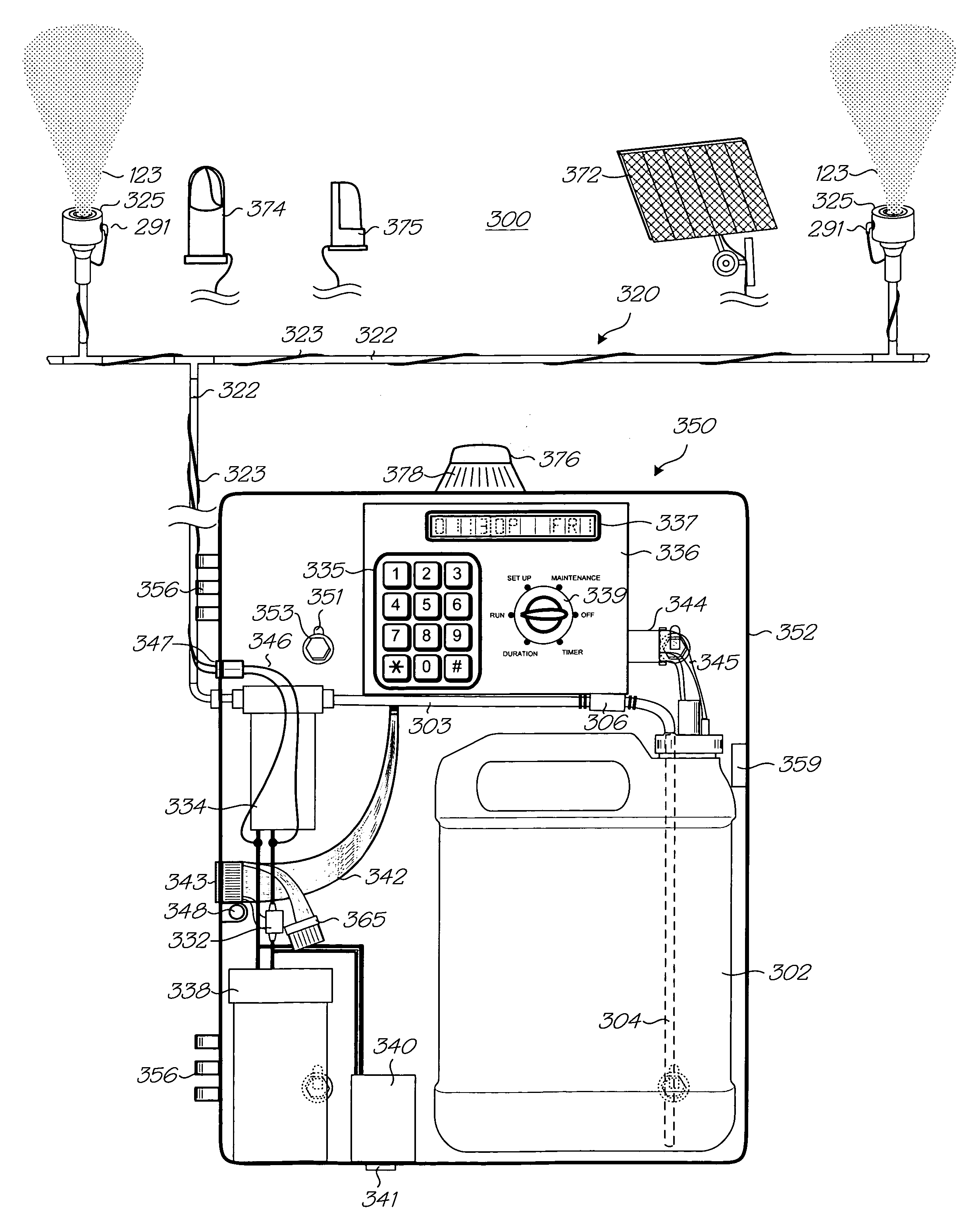
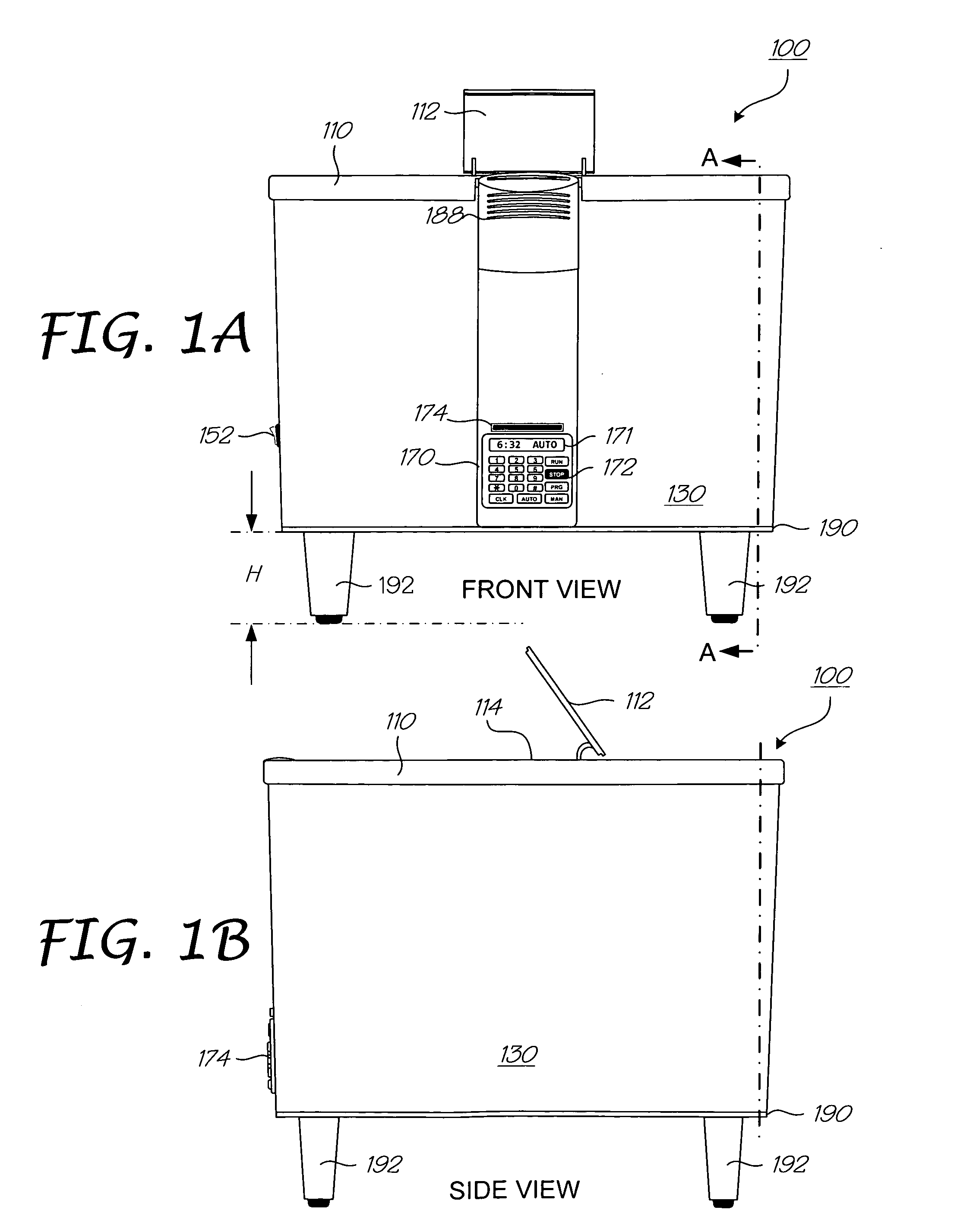
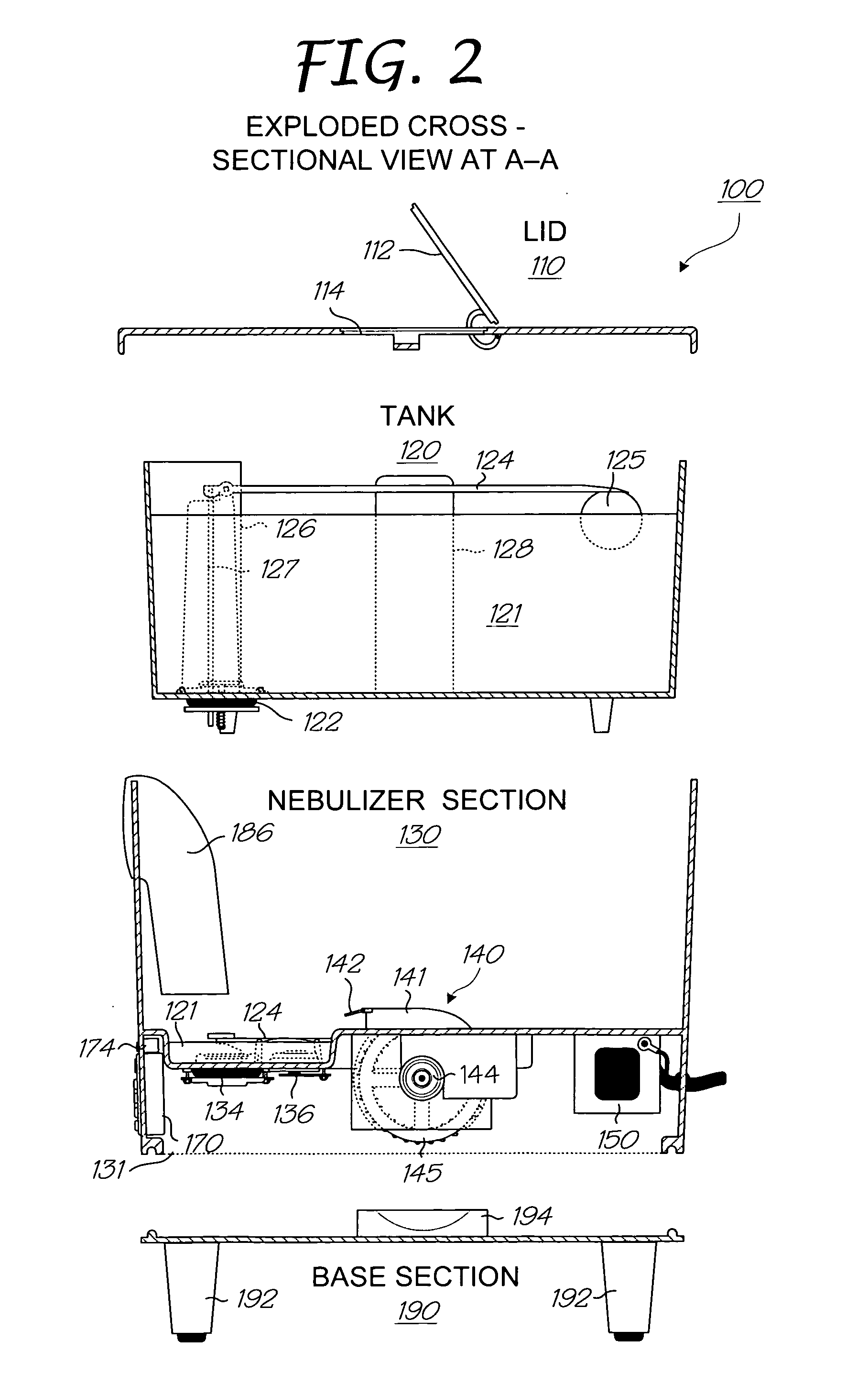
Element Reference Number Designations100:Ultrasonic Humidifier110:Lid Section112:Tank Fill Cover114:Tank Fill Opening120:Tank Section121:Repellant122:Tank Valve123:Repellant Vapor124:Tank Float Assembly125:Tank Float126:Float Assembly Pedestal127:Switch Actuating Rod128:Tank Handle130:Humidifier Section131:Nebulizer Volume132:Repellant Well133:Sump134:Ultrasonic Transducer Assembly135:Ultrasonic Transducer Assembly136:Well Level Switch137:Well Level Sensor138:Tank Level Switch139:Tank Level Switch Cover140:Fan141:Fan Shroud142:Shroud Louver143:Fan Motor Support144:Fan Motor145:Fan Impeller146:Optional Battery147:Optional Battery Charger / Rectifier148:Optional Low Voltage Input150:Transformer151:AC Input152:GFI Power Switch163:Well Float Contact164:Well Float Assembly165:Well Float166:Well Assembly Pedestal170:Control Panel171:Display172:Panel Input Buttons / Switches174:Motion Sensor175:Transducer Case176:Transducer Seal177:Metal Disk178:Transducer (Piezoelectric Crystal)179:Cera...


PUM


Abstract

The present invention is directed to an ultrasonic repellent humidifier for dispersing insect repellant into the air as a micro fine repellent vapor. A repellent tank provides rhodinol and cedarwood oil based repellent to a repellent well. An ultrasonic transducer is positioned in the well beneath the level of the repellent. It vibrates, forming a repellant vapor that is drawn into a vapor duct by a forced air system and out of the unit, dispersing the repellent vapor into the surrounding air. The vibrating portion of the ultrasonic transducer that is exposed to the oil-based repellent is a ceramic material that inhibits residue from forming on the transducer that reduces its efficiency. The ceramic material may be formed on the metal case of the transducer or on the piezoelectric oscillation crystal, or it may be a separately replaceable disc.

Description

CROSS-REFERENCE TO RELATED APPLICATIONS[0001]This application is a continuation in part, related to and claims the benefit of priority to currently pending U.S. patent application Ser. No. 11 / 985,816 filed Nov. 16, 2007, entitled “Ultrasonic Humidifier for Repelling Insects,” which is assigned to the assignee of the present invention. This application is also related to U.S. patent application Ser. No. 11 / 524,073 filed Sep. 20, 2006, entitled “Automated Pest Misting System With Pump,” which is assigned to the assignee of the present invention. The above identified application is incorporated by reference herein in its entirety.BACKGROUND OF THE INVENTION[0002]The present invention relates generally to a device for repelling insects. More particularly, the present invention relates to an ultrasonic humidifier for dispersing insect repellant into the air.[0003]Many types of insects and other nuisance bugs are considered pests, because they transmit diseases, damage structures or destr...

Claims


Application Information

Patent Timeline
IPC IPC(8): A01M7/00A01M13/00
CPCA01M29/12A01M1/205B05B17/0684B05B17/0661B05B17/0615B05B7/0012H10N30/883
Inventor MODLIN, KEMPER O'NEALJOHNNIEKERK, LEO
Owner MONSTER MOSQUITO SYST
Why Eureka
Eureka Blog
Learn More