
Optical Transmission Between a Central Terminal and a Plurality of Client Terminals via an Optical Network

Active Publication Date: 2010-09-02
ORANGE SA (FR)
View PDF13 Cites 15 Cited by
  • Summary
  • Abstract
  • Description
  • Claims
  • Application Information

AI Technical Summary

Benefits of technology

[0011]Objects of the invention are to eliminate those drawbacks and to simplify optical transmission between a central terminal and a plurality of client terminals.

Problems solved by technology

Optical technologies are currently very little used access networks because the infrastructure cost as generated in particular by installing optical fibers between central offices and subscribers, is still prohibitive.
However, the use of optical technologies in access networks based on passive optical network architectures represents a significant step forward in terms of capacity, impossible to achieve with cable access technologies, but nevertheless inevitable given the increasing bit rates of services aimed at the subscriber.
However, the client terminal is complex and the attenuation of the signal by a 1×N coupler is non-negligible.
Moreover, the fact that the information is extracted in each client terminal represents a security issue.
In contrast, because it uses more wavelengths and a routing component (an optical demultiplexer) that is more costly than a simple 1×N coupler, it is more costly.

Method used


Image

  • Optical Transmission Between a Central Terminal and a Plurality of Client Terminals via an Optical Network
  • Optical Transmission Between a Central Terminal and a Plurality of Client Terminals via an Optical Network
  • Optical Transmission Between a Central Terminal and a Plurality of Client Terminals via an Optical Network

Examples


first embodiment

[0169]FIG. 4 shows a first embodiment of a bidirectional optical transmission system comprising an uplink and a downlink using the uplink and downlink transmission stages described above and in which the central terminal 100 comprises a receive demultiplexer 33 (second demultiplexing means), two data receivers 37 and 35 connected to the receive demultiplexer 33, and the circulator 31, which is disposed between the converter 20 and the receive demultiplexer 33.

[0170]During a demultiplexing step of the uplink transmission stage, the wavelength division multiplexed uplink optical signal S′f is spectrally demultiplexed by the receive demultiplexer 33 to distribute the spectral components S′1, S′2 to first and second data receivers 35, 37, respectively.

[0171]During a reception step, the first data receiver 35 and the second data receiver 37 receive the uplink data D′1 and the uplink data D′2, respectively, carried by the uplink optical signals S′1 and S′2, respectively, on respective wav...

second embodiment

[0175]In the second embodiment shown in FIG. 5, the central terminal 101 comprises:[0176]the transmitter 30, the optical circulator 31;[0177]a first optical converter 20 of the invention, between the transmitter 30 and the optical circulator 31;[0178]a data receiver 39 connected to the second converter 21; and[0179]a second optical converter 21 of the invention, between the data receiver 39 and the optical circulator 31.

[0180]After it has been routed by the optical circulator 31, the wavelength division multiplexed uplink optical signal S′f is injected into the second optical converter 21, which in a step of conversion by the non-linear soliton trapping effect converts it into a time division multiplexed uplink signal on a single wavelength λ′0 carrying the uplink data D′1, D′2.

[0181]As in the downlink transmission stage, the non-linear optical means of the second converter 21 consist of a polarization-maintaining birefringent fiber 5. The conversion step of the uplink transmission ...


PUM


Abstract

A system and an associated method of bidirectional optical transmission between a central terminal (101) and a plurality of client terminals (11, 12) via a passive optical network (PON) (3), wherein the conversion of an OTDM signal into a WDM signal (respectively the conversion of a WDM signal into an OTDM signal) is effected by an optical converter (20) (respectively 21) by a soliton trapping effect during a downlink (respectively uplink) transmission stage.

Description

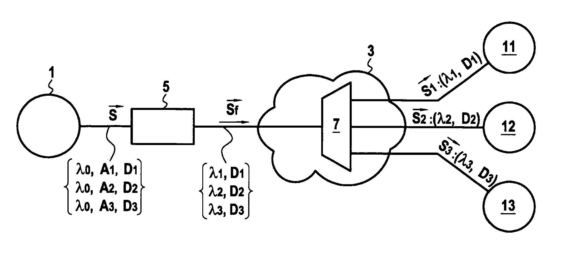
TECHNICAL FIELD OF THE INVENTION[0001]The field of the invention is that of access networks that take the form of passive optical networks (PON). The invention is more particularly concerned with very high bit rate optical transmission systems linking a central terminal and a plurality of client terminals via an access passive optical network.BACKGROUND OF THE INVENTION[0002]At present, the access networks of most telecommunications operators use cable, access technologies such as ADSL (Asymmetrical Digital Subscriber Line). Optical technologies are currently very little used access networks because the infrastructure cost as generated in particular by installing optical fibers between central offices and subscribers, is still prohibitive.[0003]However, the use of optical technologies in access networks based on passive optical network architectures represents a significant step forward in terms of capacity, impossible to achieve with cable access technologies, but nevertheless inev...

Claims


Application Information

Patent Timeline
IPC IPC(8): H04J14/02H04B10/25H04B10/2581H04B10/27H04B10/272H04B10/524H04B10/58
CPCH04J7/00H04J14/0226H04J14/025H04J14/08H04J14/0246H04J14/0282H04B10/2581H04J14/02
Inventor PINCEMAN, ERWANPAYOUX, FRANCK
Owner ORANGE SA (FR)
Learn More