
Method for etching 3D structures in a semiconductor substrate, including surface preparation

Inactive Publication Date: 2010-08-26
INTERUNIVERSITAIR MICRO ELECTRONICS CENT (IMEC VZW)
View PDF11 Cites 2 Cited by
  • Summary
  • Abstract
  • Description
  • Claims
  • Application Information

AI Technical Summary

Benefits of technology

[0004]Methods of the preferred embodiments may provide an easy and cost friendly solution to avoid grass formation and an alternative to the costly and time consuming CMP step and thereby avoiding the problem of grass formation. More particularly, the methods of the preferred embodiments may remove the cause of the micro-masking without applying a CMP step.
[0015]It is an advantage of a method according to preferred embodiments that a supplementary time-consuming and expensive chemical mechanical polishing step after grinding can be avoided. It is a further advantage of the method according to preferred embodiments that no additional tool is needed and the surface treatment in order to prevent / avoid grass formation can be performed in the same (etch) chamber in which the subsequent DRIE etching of 3D structures is performed.

Problems solved by technology

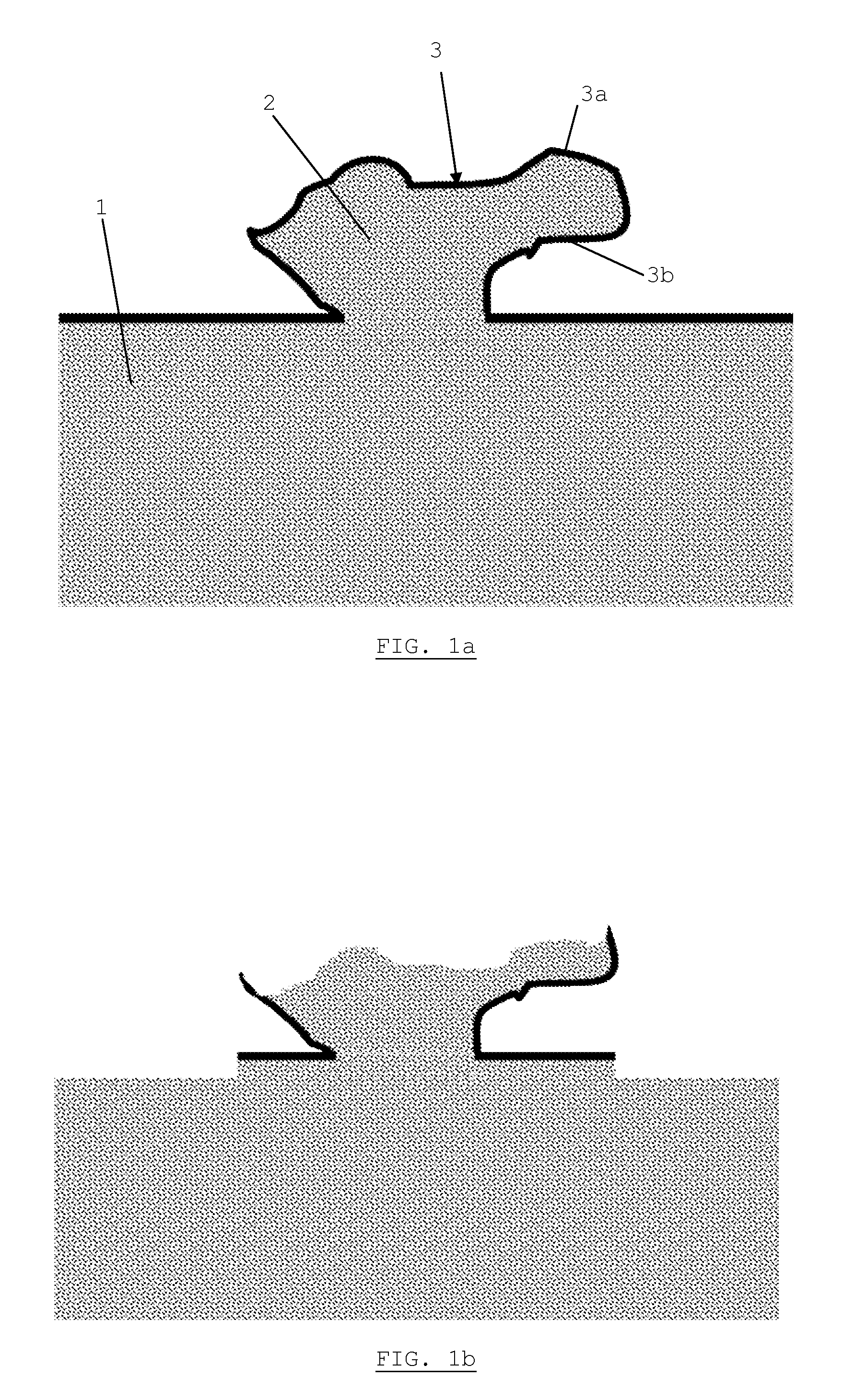
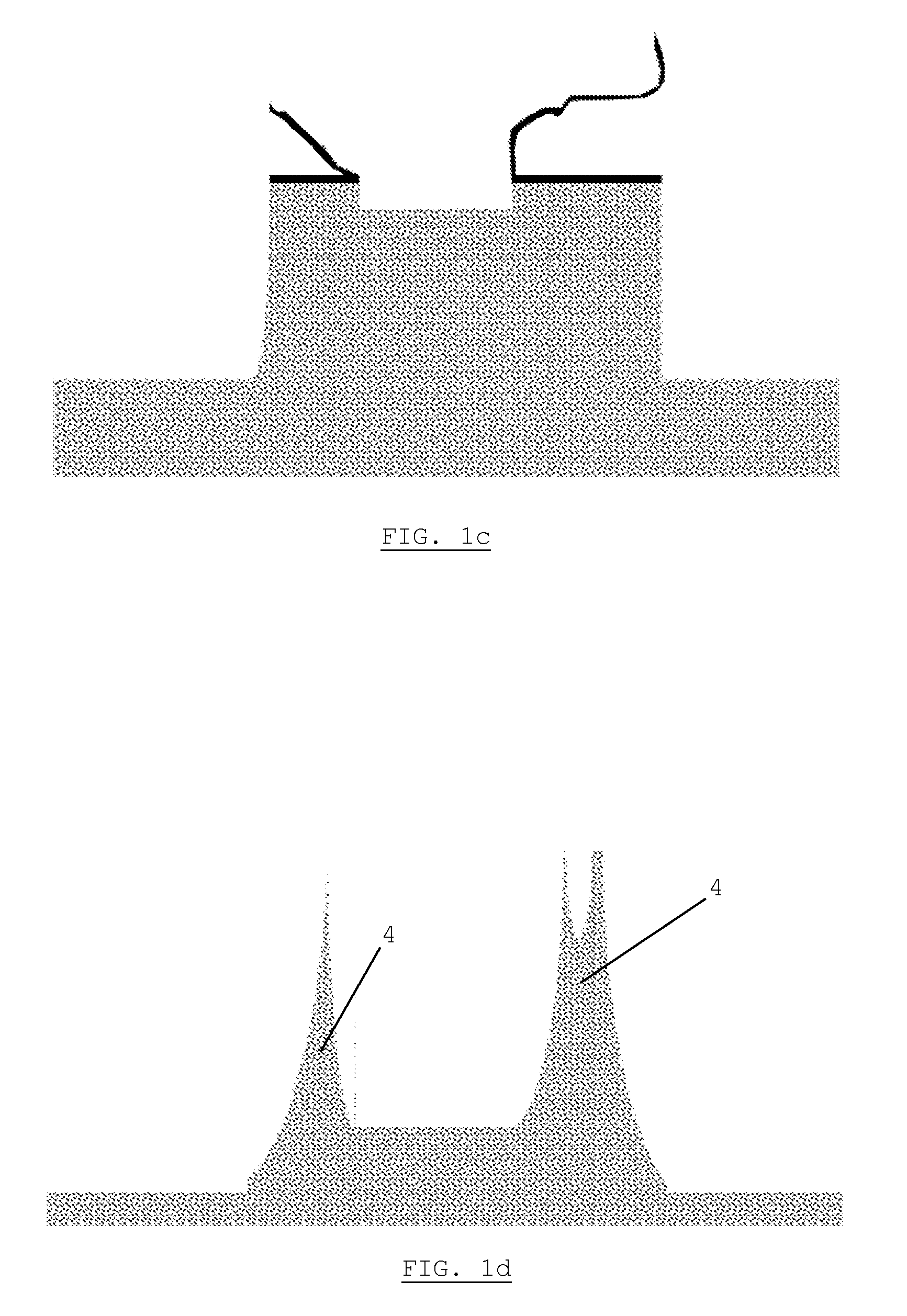
When this final thinning step is omitted, the subsequent Deep Reactive Ion Etching (DRIE), directly performed on ground surfaces, will suffer from the fact that even the smallest roughness caused by the ultra fine grinding processes can lead to detrimental effects on the DRIE, especially through so-called “grass formation”.

Method used


Image

  • Method for etching 3D structures in a semiconductor substrate, including surface preparation
  • Method for etching 3D structures in a semiconductor substrate, including surface preparation

Examples


Embodiment Construction

[0017]The present invention will be described with respect to particular embodiments and with reference to certain drawings but the invention is not limited thereto but only by the claims. The drawings described are only schematic and are non-limiting. In the drawings, the size of some of the elements may be exaggerated and not drawn on scale for illustrative purposes. The dimensions and the relative dimensions do not correspond to actual reductions to practice of the invention.

[0018]Moreover, the term top and the like in the description and the claims are used for descriptive purposes and not necessarily for describing relative positions. It is to be understood that the terms so used are interchangeable under appropriate circumstances and that the preferred embodiments described herein are capable of operation in other orientations than described or illustrated herein.

[0019]It is to be noticed that the term “comprising”, used in the claims, should not be interpreted as being restri...


PUM


Abstract

A method is provided for producing 3D structures in a semiconductor substrate using Deep Reactive Ion Etching (DRIE), comprising at least the steps of: providing a substrate, and then grinding the backside of the substrate in order to achieve a thinned substrate, wherein extrusions and native oxides are left after said grinding step, and then performing a surface treatment selected from the group consisting of a wet etching step and a dry etching step in order to remove at least said native oxides and extrusions on the surface of said backside of the substrate which are causes for the grass formation during subsequent etching, and then performing deep reactive ion etching in order to achieve 3D vias.

Description

CROSS-REFERENCE TO RELATED APPLICATIONS[0001]This application claims the benefit under 35 U.S.C. §119(e) of U.S. provisional application Ser. No. 61 / 155,426, filed Feb. 25, 2009, the disclosure of which is hereby expressly incorporated by reference in its entirety and is hereby expressly made a portion of this application.FIELD OF THE INVENTION[0002]The preferred embodiments relate to the field of semiconductor processing, in particular to the process known as Deep Reactive Ion Etching (DRIE), which is used to produce deep vias in a semiconductor (primarily Si) substrate. More particularly, the preferred embodiments relate to a surface treatment method after a grinding process step in order to avoid unwanted residuals which may lead to unwanted “grass formation” during the DRIE step.BACKGROUND OF THE INVENTION[0003]Deep reactive ion etching (DRIE) of Si is one of the most important process steps for fabrication of different sensors and actuators and for 3D integration. For some appl...

Claims


Application Information

Patent Timeline
IPC IPC(8): H01L21/304
CPCH01L21/02057H01L21/3065H01L21/304
Inventor VERDONCK, PATRICKVAN CAUWENBERGHE, MARCPHOMMAHAXAY, ALAINCOTRIN TEIXEIRA, RICARDOTUTUNJYAN, NINA
Owner INTERUNIVERSITAIR MICRO ELECTRONICS CENT (IMEC VZW)
Learn More