
Touch sensitive input device

a technology of input device and sensing electrode, which is applied in the direction of electronic switching, pulse technique, instruments, etc., can solve the problem of very small capacitance between a human finger and the sensing electrode, and achieve the effect of low cost, small capacitance between a human finger and the sensing electrode, and low cos

Inactive Publication Date: 2010-08-26
NG SHEK WAI
View PDF3 Cites 0 Cited by
  • Summary
  • Abstract
  • Description
  • Claims
  • Application Information

AI Technical Summary

Benefits of technology

[0008]Accordingly, an object of the present invention is to provide a low cost touch input device. The difficulty associated with capacitive touch input devices is that the capacitance between a human finger and the sensing electrode is very small. However, we may make use of the principle that the impedance of a capacitor decreases with the frequency of the signal across the capacitor. If there is a signal whose magnitude is comparable to the AC mains but has a higher frequency, we may have a low cost touch input device whose cost is comparable to those used for lighting control.
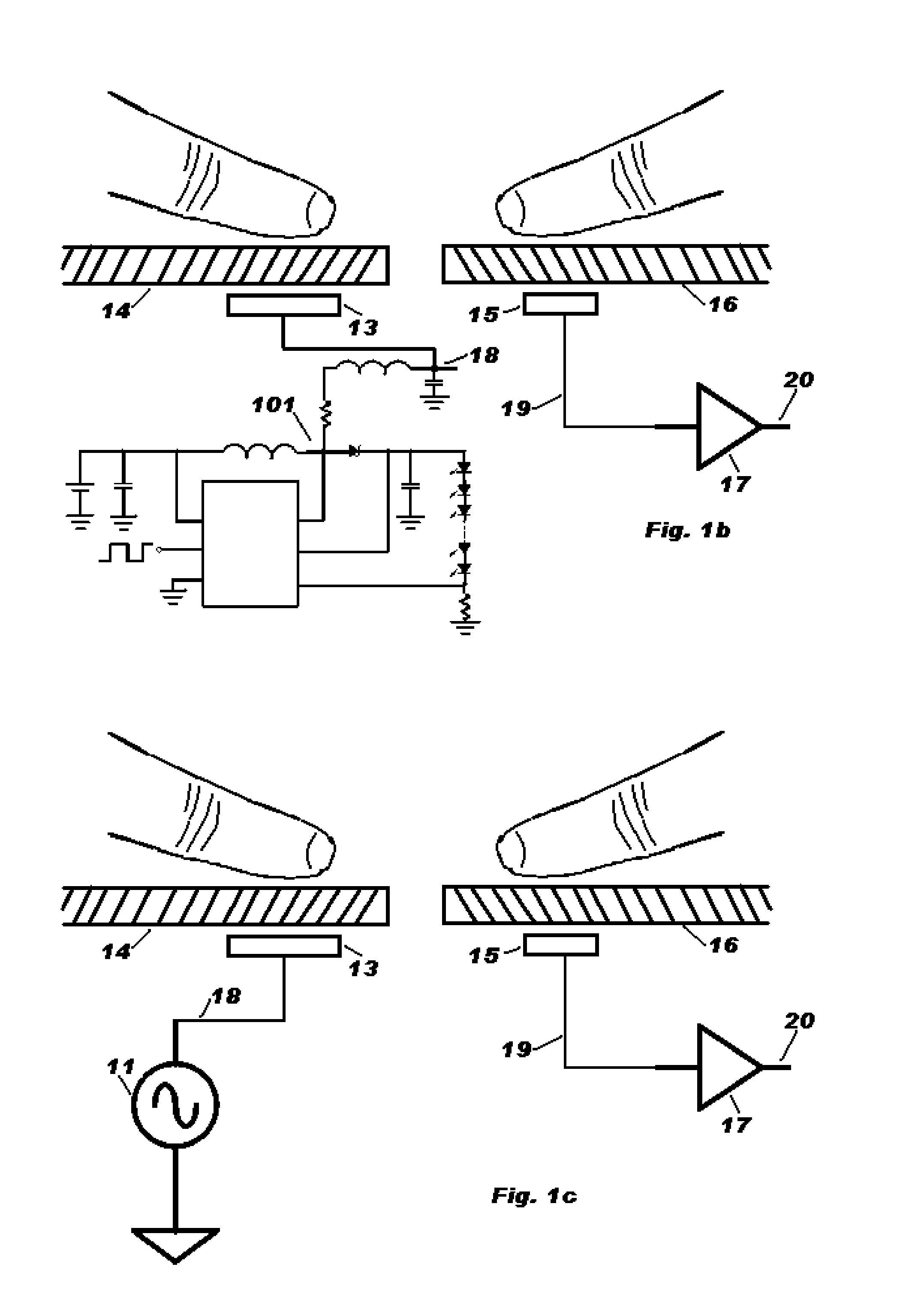
[0011]In the case that the back light does not use high voltage, one may still use a simple oscillator to generate the needed high voltage and high frequency signal. Since the output current needed is in micro ampere range, the oscillator can be very simple. The implementation still can be very low cost.

Problems solved by technology

The difficulty associated with capacitive touch input devices is that the capacitance between a human finger and the sensing electrode is very small.

Method used


Image

  • Touch sensitive input device
  • Touch sensitive input device
  • Touch sensitive input device

Examples


Embodiment Construction

[0021]The invention will now be described by the following embodiments. These embodiments are not intended to limit the scope of the present invention but are to demonstrate the invention only. All features and combinations described in the embodiments are not necessarily essential to the invention.

[0022]The preferred embodiments of the present invention and their advantages are best understood by referring to FIGS. 1-5c of the drawings. Like numerals are used for like and corresponding parts of the various drawings.

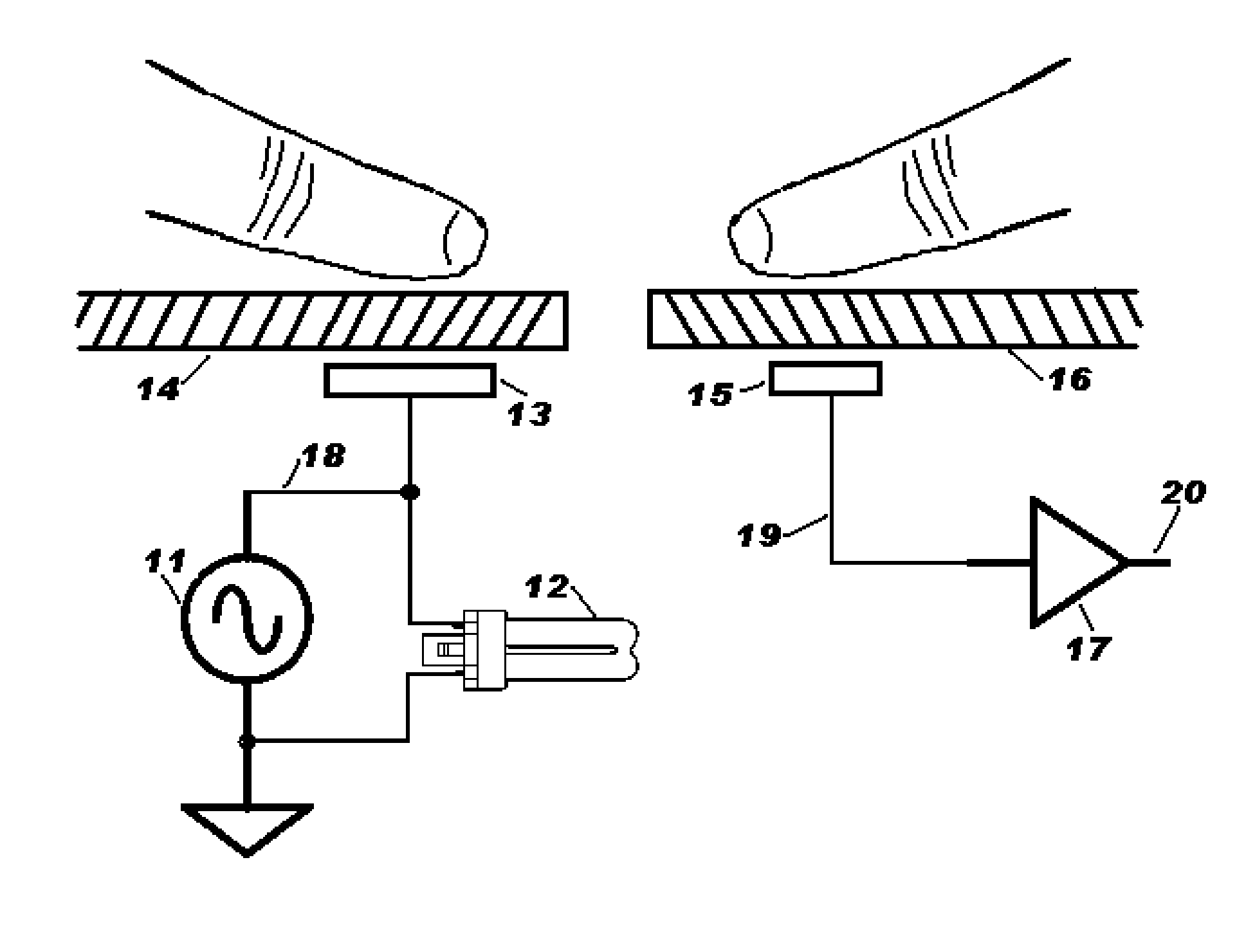
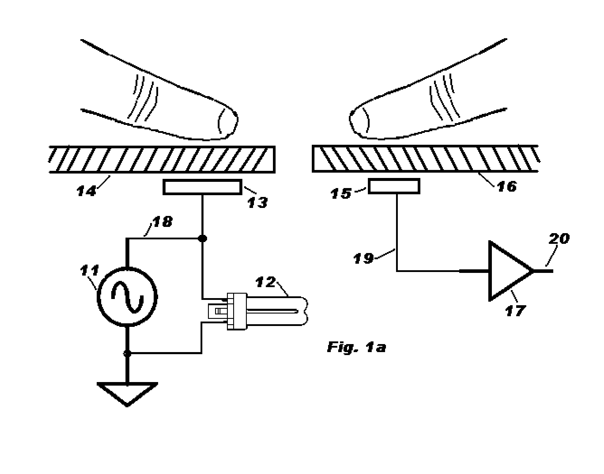
[0023]FIG. 1a illustrates an embodiment of the present invention when the electronic apparatus under control is equipped with a fluorescent lamp 12. The powers source 11 is a high voltage and high frequency signal. The typical voltage is 400V peak and the typical frequency is 75 kHz. This signal 18 is connected to the sourcing plate 13 which is mounted under a dielectric layer 14. On the other side of FIG. 1a is a sensing electrode 15 which is also mounted under another ...


PUM


Abstract

The power source of back lighting device, e.g. a fluorescent lamp, inside typical electronic products is a high voltage and high frequency signal. This invention makes use of this characteristic to provide a low cost touch input device. The characteristic allows the signal to penetrate thick dielectric layers, e.g. a glass plate or the casing, to trigger a sensing circuit. Thus, the sensing circuit can be a simple logic gate and the implementation cost is low.

Description

FIELD OF INVENTION[0001]This invention relates to the field of touch input devices.BACKGROUND OF INVENTION[0002]There are many kinds of touch input devices. However, their working principles and costs are quite different. Touch control switches used in controlling lighting make use of the AC mains and the cost is the lowest. However, it is only workable on devices connected to the AC mains. Furthermore, this method works best when there is direct contact between the sensing electrode and a human finger.[0003]Portable electronic products powered by battery use capacitive or resistive touch input devices. A resistive input device uses an expensive touch panel and calculates the touch position by using the resistance between edges of the panel and the touch point. However, the low transparency of the panel is a disadvantage.[0004]A capacitive input device uses complex circuitry to detect the change in grounding capacitance when a finger is in the proximity of a sensing electrode. In U....

Claims


Application Information

Patent Timeline
Patent Type & Authority Applications(United States)
IPC IPC(8): G06F3/045
CPCG06F3/041H03K17/962G06F3/044
Inventor NG, SHEK-WAI
Owner NG SHEK WAI
Learn More