
Variable displacement compressor

Inactive Publication Date: 2010-08-19
SANDEN CORP
View PDF11 Cites 1 Cited by
  • Summary
  • Abstract
  • Description
  • Claims
  • Application Information

AI Technical Summary

Benefits of technology

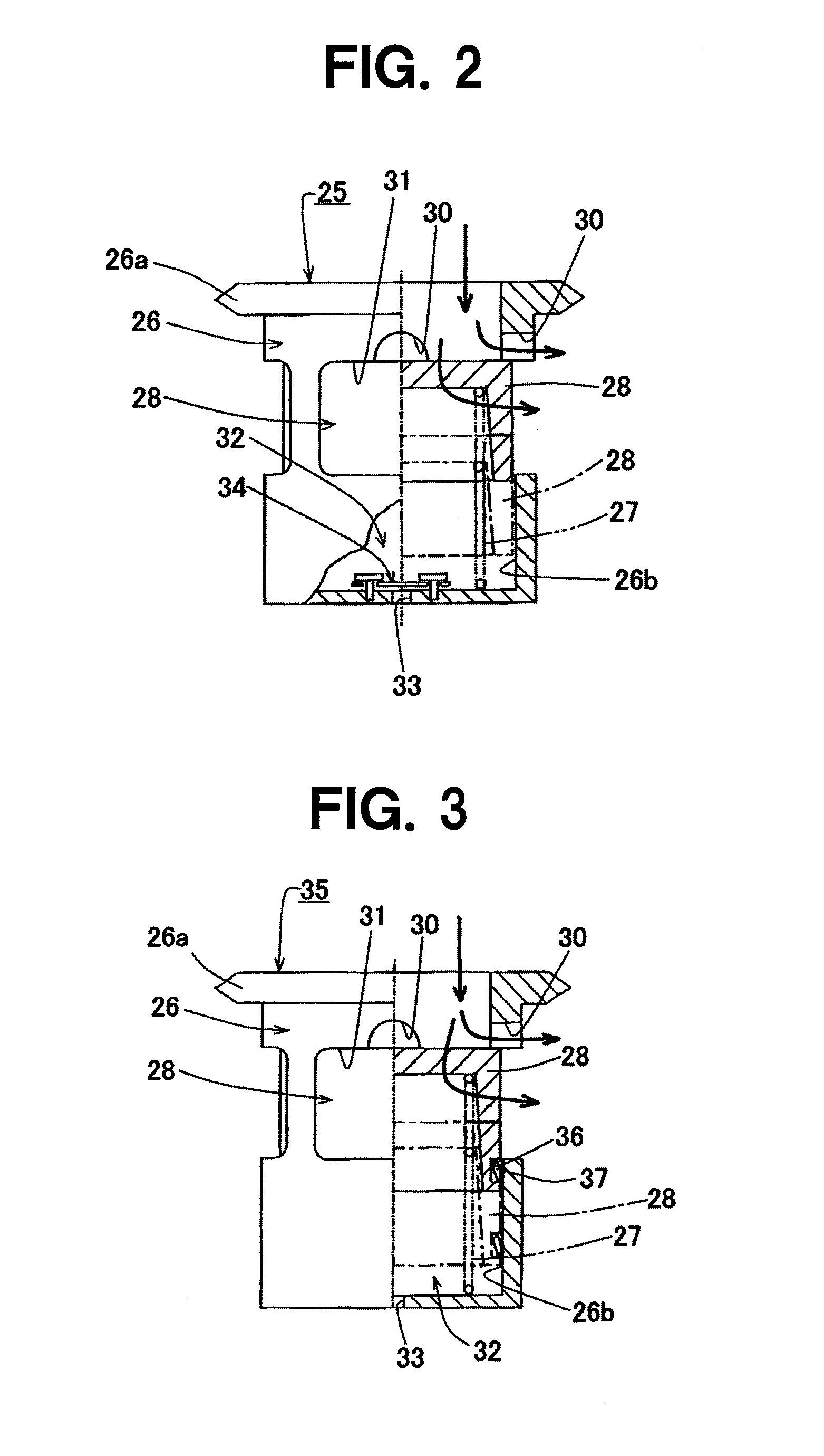
[0008]In the present invention, because the resistance against the movement of the valve body in the direction of increasing the opening area of the flow passage is made to be greater than the resistance against the movement in the direction of decreasing the opening area, even if there exists liquid refrigerant at the compressor startup, etc., an inconvenience that the liquid refrigerant is sucked into the compressor at once is prevented, so that the liquid compression can be surely prevented. In addition, because the resistance through the opening-degree adjustment valve is greater in the direction of increasing the opening area of the flow passage, the pressure loss in a downstream site increases when the engine rotation speed increases. Therefore, because the differential pressure between the internal pressure of the crank chamber and the internal pressure of the suction chamber increases, the discharge displacement can decrease quickly to decrease an excessive power generation, so that the response of the displacement control can be improved.

Problems solved by technology

Therefore, when there exists liquid refrigerant in an evaporator of the air conditioning system for vehicle at the compressor startup, etc., it may be caused that opening-degree adjustment valve 100 operates as the compressor starts up so as to rapidly increase the opening area of the flow passage and the liquid refrigerant in the evaporator flows into the compressor at once, causing the liquid compression, so as to adversely affect the compressor.
Until the discharge displacement has been controlled to decrease, especially in a case where the movement to control the displacement delays, the refrigerant flow rate is increased by the amount multiplied by the engine rotation speed increase and the discharge displacement, so that the power consumption increases.
Therefore, there might be a bad influence on an engine control and an acceleration performance of the vehicle.

Method used


Image

  • Variable displacement compressor
  • Variable displacement compressor
  • Variable displacement compressor

Examples


Embodiment Construction

[0062]Hereinafter, desirable embodiments of a variable displacement compressor according to the present invention will be explained referring to figures.

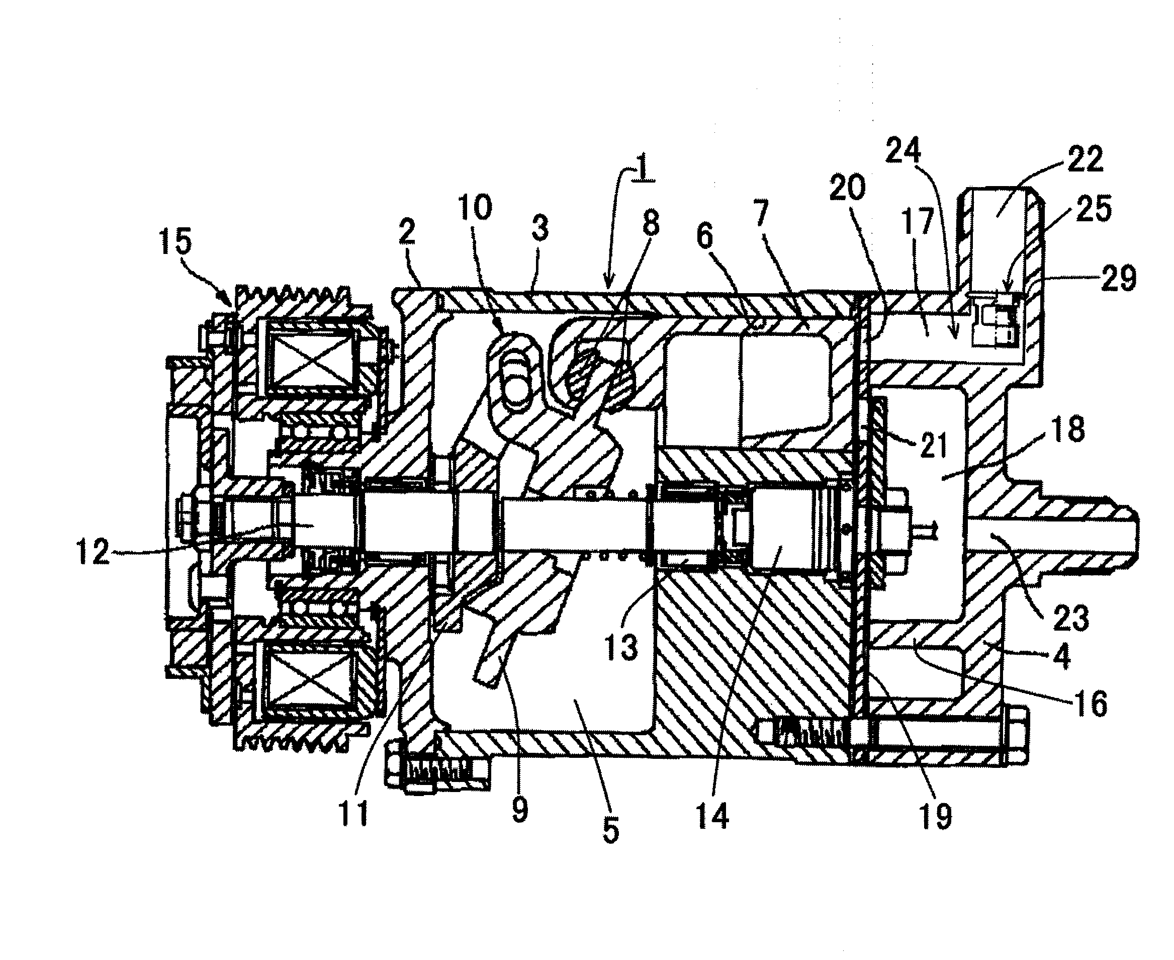
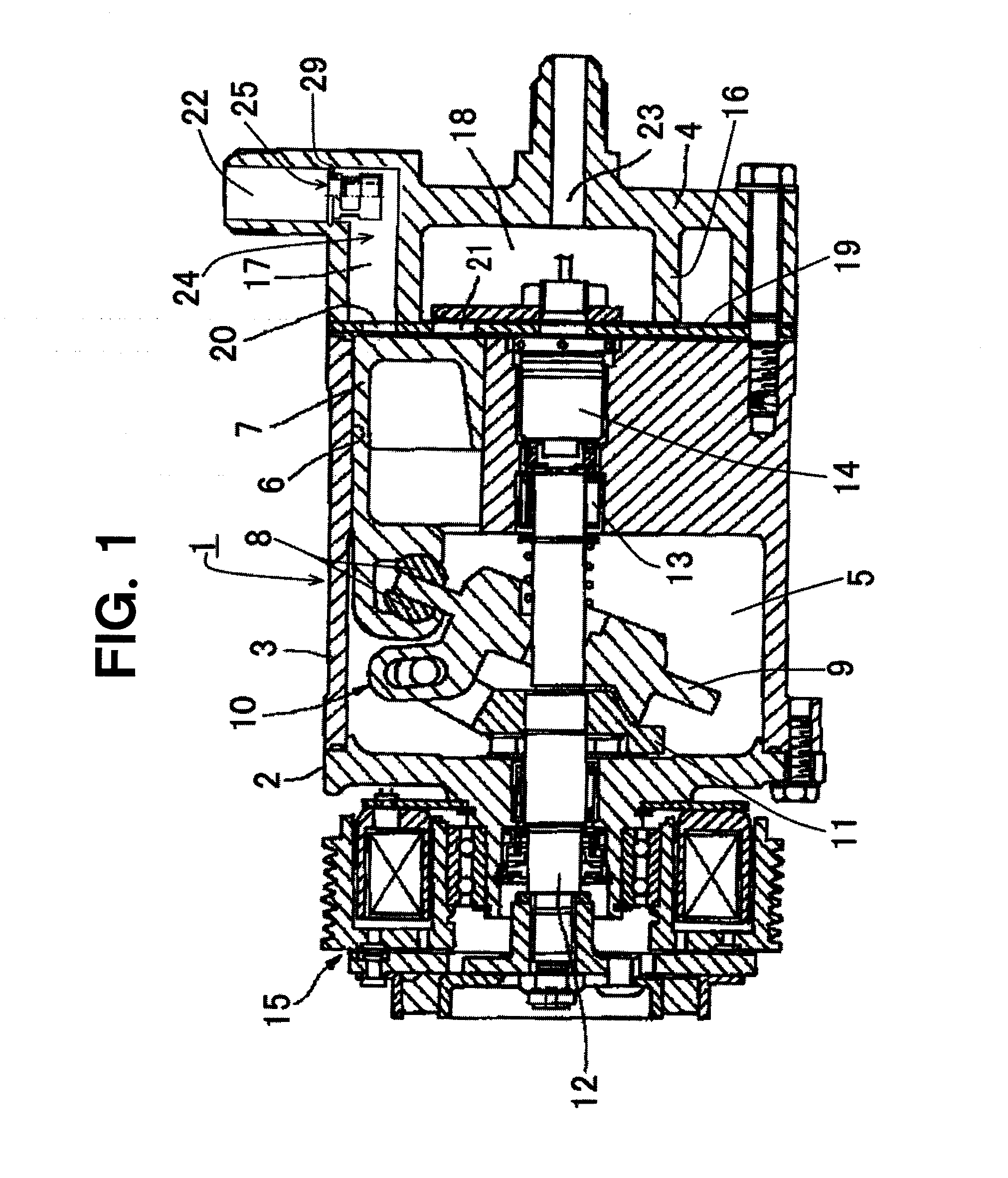
[0063]FIG. 1 shows a variable displacement compressor according to the first embodiment of the present invention. Besides, variable displacement compressors in the embodiments to be described are composed as variable displacement compressors used for a refrigeration circuit of air conditioning system for vehicles. In FIG. 1, variable displacement compressor 1 has front housing 2, cylinder block 3 and cylinder head 4. Crank chamber 5 is formed between front housing 2 and cylinder block 3. Plural cylinder bores 6 are provided along a circumferential direction. Piston 7 is inserted reciprocably in each cylinder bore 6. Swash plate 9 contacts slidably with one end of piston 7 through a pair of shoes 8. Swash plate 9 of which inclination angle is provided to be variable is coupled with rotor 11 which rotates integrally with drive shaft 1...


PUM


Abstract

A variable displacement compressor comprises an opening-degree adjustment valve which is disposed in a flow passage between a suction port and a suction hole communicating with a cylinder bore and variably controls the opening area of the flow passage. The variable displacement compressor is characterized in that the resistance against the movement of the valve body of the opening-degree adjustment valve in the direction of increasing the opening area of the flow passage is made to be greater than the resistance against the movement thereof in the direction of decreasing the opening area. The liquid compression at the starting of the compressor is prevented from occurring, whereby the durability and the reliability of the device can be improved and the device can exhibit excellent displacement control responsiveness.

Description

TECHNICAL FIELD OF THE INVENTION[0001]The present invention relates to a variable displacement compressor having an opening-degree adjustment valve which variably controls an opening area of a flow passage, which is also called a suction passage, in the flow passage between a suction port and a suction hole communicating with a cylinder bore, and specifically, relates to a variable displacement compressor which is suitable as a compressor provided in a refrigeration circuit of an air conditioning system for vehicles.BACKGROUND ART OF THE INVENTION[0002]An opening-degree adjustment valve which variably controls an opening area of a flow passage and which is provided in a flow passage between a suction port and a suction hole communicating with a cylinder bore, of a compressor of an air conditioning system for vehicles, etc., such as shown in FIG. 6, is known. In FIG. 6, symbol 100 implies an opening-degree adjustment valve, and opening-degree adjustment valve 100 having casing 101 an...

Claims


Application Information

Patent Timeline
IPC IPC(8): F04B49/22
CPCF04B27/1009F04B2027/1881F04B49/225F04B27/1804
Inventor TAKAI, KAZUHIKO
Owner SANDEN CORP
Learn More