Volume correction device, volume correction method, volume correction program, and electronic equipment

a volume correction and volume correction technology, applied in the field of volume correction devices, volume correction methods, volume correction programs, can solve the problems of existing volume control to be achieved using the agc method, confronted with a problem, and the above-mentioned problems, so as to prevent the fluctuation of sounds during the steady-state audio interval, the mean level of the audio signal is kept constant, and the effect of large level differences

Inactive Publication Date: 2010-08-19
SONY CORP
View PDF2 Cites 23 Cited by
  • Summary
  • Abstract
  • Description
  • Claims
  • Application Information

AI Technical Summary

Benefits of technology

[0019]When the time constant for detection of the mean level of an audio signal is set to a small value, an output volume can be held constant by swiftly coping with a change in the output volume represented by the audio signal. Therefore, for example, at the leading time point of a commercial message portion, at the time of a change of scenes, or at a time point at which a level difference is noticeable, a change in an output volume is expected to be nullified in order to hold the output volume constant.
[0055]According to the further another embodiment of the present invention, when loud sounds other than voice are inputted, volume correction can be achieved to quickly lower the level of an audio signal so as to correct the volume.

Problems solved by technology

The foregoing problem arises not only in a case where signals representing different contents obtained before and after pieces of input equipment or receiving channels are switched have a level difference but also in a case where the same content is being received.
This may be found disgusting.
However, the existing volume control to be achieved using the AGC method is confronted with a problem described below.

Method used


Image

  • Volume correction device, volume correction method, volume correction program, and electronic equipment
  • Volume correction device, volume correction method, volume correction program, and electronic equipment
  • Volume correction device, volume correction method, volume correction program, and electronic equipment

Examples


first embodiment

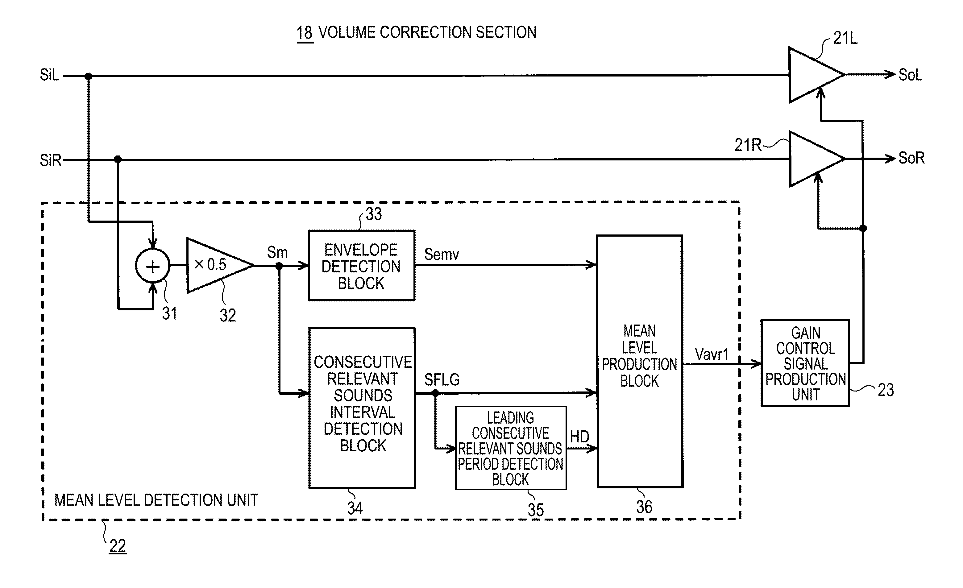
[0103]FIG. 1 is a block diagram showing an example of the overall configuration of the volume correction section 18 that is the volume correction device in accordance with the first embodiment of the present invention.

[0104]As shown in FIG. 1, even in the present embodiment, the input audio signals SiL and SiR on the two left and right channels are fed to variable gain amplifiers 21L and 21R whose gains are varied or controlled according to a gain control signal.

[0105]The input audio signals SiL and SiR on the two left and right channels are fed to a mean level detection unit 22. As described later, the mean level of an entire audio signal, which is a sum signal of the input audio signals SiL and SiR on the two left and right channels, attained during a consecutive relevant sounds interval is detected.

[0106]What is referred to as a consecutive relevant sounds interval is an interval, during which an audio signal is present, in the sum signal of the input audio signals SiL and SiR. I...

second embodiment

[0176]The second embodiment is a variant of the foregoing first embodiment. In the first embodiment, the time constant for mean level detection employed during the leading period of a consecutive relevant sounds interval includes only one kind of time constant. In the second embodiment, the time constant for mean level detection employed during the leading period of the consecutive relevant sounds interval is varied depending on whether the mean level detected during the succeeding consecutive relevant sounds interval is higher or lower than the mean level detected during the preceding consecutive relevant sounds interval.

[0177]For example, when the level of an audio signal abruptly increases, if volume control is implemented to rapidly suppress the increase, a sound fluctuation occurs at the level change time point. There is a fear that the sound fluctuation may give an unnatural feeling. When the mean level attained during the succeeding consecutive relevant sounds interval gets h...

third embodiment

[0194]For example, when it comes to a television broadcast or a movie content recorded in a recording medium, an audio signal represents numerous kinds of sounds including human voice, background music (BGM), and sound effects. When a user uses a remote control or the like to manually control a volume, the level of the audio signal is often adjusted with a signal level of a component of the audio signal, which represents the human voice, as a reference so that lines will be properly audible.

[0195]The aforesaid volume correction method is a method of achieving volume control by monitoring the level of an entire audio signal. For example, when volume control is implemented based on an AGC method with the mean level of the audio signal as a reference, volume control is performed on the entire audio signal so that a loud sound will not be released or an inaudible small-volume sound will be audible.

[0196]However, when the volume of human voice is intently heard, the volume of human voice...


PUM


Abstract

A volume correction device includes: a variable gain means for controlling a gain, given to an input audio signal, according to a gain control signal; a consecutive relevant sounds interval detection means for detecting a consecutive relevant sounds interval, during which a group of temporally adjoining consecutive relevant sounds is present, in the input audio signal; a mean level detection means for detecting the mean level of the input audio signal attained during the consecutive relevant sounds interval, and whose time constant for mean level detection is set to a smaller value during the leading period of the consecutive relevant sounds interval than during the remaining period; a gain control signal production means for producing the gain control signal, so that the mean level will be equal to a reference level, and feeding the gain control signal to the variable gain means.

Description

BACKGROUND OF THE INVENTION[0001]1. Field of the Invention[0002]The present invention relates to a volume correction device, a volume correction method, and a volume correction program that are preferably adapted to an audio output section of electronic equipment represented by, for example, a television set.[0003]2. Description of the Related Art[0004]When broadcast channels to be received by a television set are switched, or when plural pieces of input equipment are switched at an audiovisual (AV) center in an AV system, a large change may occur in an output volume due to a difference in a level between contents.[0005]In such a case, if a user wants to obtain a volume he / she likes, the user has to perform a volume adjusting manipulation using a remote control or the like so as to control the volume. The user may find it time-consuming.[0006]An example of a technique for solving the above problem is disclosed in patent document 1 (Japanese Patent No. 3475476). According to the pate...

Claims


Application Information

Patent Timeline
Patent Type & Authority Applications(United States)
IPC IPC(8): H03G3/00G10L11/06G10L25/93
CPCH03G3/3005H04N21/4394H04N21/439H04N5/60
Inventor NOGUCHI, MASAYOSHI
Owner SONY CORP
Why Eureka
Try Eureka