
Supplemental power source

a technology of supplemental power source and micro-wind turbine, which is applied in the direction of sustainable buildings, machines/engines, and electric generator control, etc., to achieve the effects of increasing the efficiency of micro-wind turbine, increasing the efficiency of the turbine, and extracting more power

Inactive Publication Date: 2010-08-19
AGLOBAL TECH
View PDF2 Cites 16 Cited by
  • Summary
  • Abstract
  • Description
  • Claims
  • Application Information

AI Technical Summary

Benefits of technology

[0040]The present invention addresses the efficient transformation of mechanical energy into electrical energy, reducing or completely eliminating the technical problems experienced by conventional conversion devices, such as wind turbines as identified above.
[0041]The inventor has discovered that the most efficient and effective way to generate electrical energy is to utilize a naturally occurring input energy source such as wind, water or other fluid. The advantage of this approach is that the input energy source usually is available at little or no cost, is renewable, and has no adverse effect on the environment. Thus, the inventor has developed a novel energy conversion device in the form of a turbine which efficiently converts mechanical energy from a fluid source, such as air and water, into electrical energy.

Problems solved by technology

As known in the prior art, this rather complex and relatively heavy equipment package usually is installed on top of tubular towers ranging in height from 150 to 300 feet.
The technical problems associated with horizontal axis wind turbines include, but are not limited to:a) Horizontal axis wind turbines cannot efficiently operate in turbulent wind conditions encountered close to the ground.
Horizontal turbines require laminar wind conditions to operate efficiently;b) The typically large dimensions of tall towers and associated blades are difficult and expensive to handle and transport.
The transportation and handling costs can range between 30% to 40% of basic hardware cost, depending on the topography of the installation site;c) Tall horizontal wind turbines are extremely expensive to install, particularly in topographically challenging and remote terrains;d) Massive tower foundation construction is required to support tall horizontal wind turbine structures;e) Maintenance of tall horizontal wind turbines is very expensive as evident from an entirely new industry that has developed to exploit these high cost;f) Tall horizontal wind turbines directly and detrimentally affect military and commercial air traffic control and safety based on their interference with radar technology;g) Environmental groups oppose horizontal wind turbines due to their adverse and detrimental impact on the population and migration of birds;h) Tall horizontal wind turbines are obtrusively visible across large areas, disrupting the appearance of the landscape and in numerous cases causing local opposition to their construction;i) Downwind variants of horizontal wind turbines are susceptible to fatigue and structural failure due to turbulence; andj) Cyclic stresses, fatigue and vibration are a major cause of failure of horizontal axis wind turbines.
The technical problems associated with vertical axis wind turbines typically include, but are not limited to, the following:a) A vertical axis wind turbine is about 50% less efficient than a horizontal wind turbine due to higher blade drag while rotating in the wind;b) As vertical axis turbines can not be packaged and installed on towers, they are not able to take advantage of stronger, more laminar, wind conditions at higher elevations;c) Like their horizontal axis counterparts, vertical axis turbines cannot efficiently operate in turbulent wind conditions typically encountered near the ground.
These guy cables add additional load to the bottom bearing of the turbine.
However, wind turbines have further limitations imposed by the laws of physics that can not be easily overcome.
Thus, the number and severity of the above noted limitations and deficiencies of traditional wind turbines make their use less than ideal in many situations.
Moreover, the use of traditional wind turbines is completely unsuited for some applications.
While each of these alternative forms of energy conversion has advantages in particular applications, they also have disadvantages in other applications.
The disadvantages have chiefly to do with the amount of energy that can be converted, physical size and cost considerations.
While batteries can be made small in size and at low cost, they are limited in the amount of electrical energy that can be converted from their chemical reaction.
Depending on their design, fuel cells can operate at higher sustained energy levels and for longer periods of time than batteries but are very expensive to manufacture.
Prior art electric generators can be designed to operate at high energy levels but also are expensive, physically large in size and required a largest amount of source energy.
Prior art approaches to solar energy conversion suffer from low conversion efficiency and, in many cases, the lack of a continuous supply of solar energy.

Method used


Image

  • Supplemental power source
  • Supplemental power source
  • Supplemental power source

Examples


Embodiment Construction

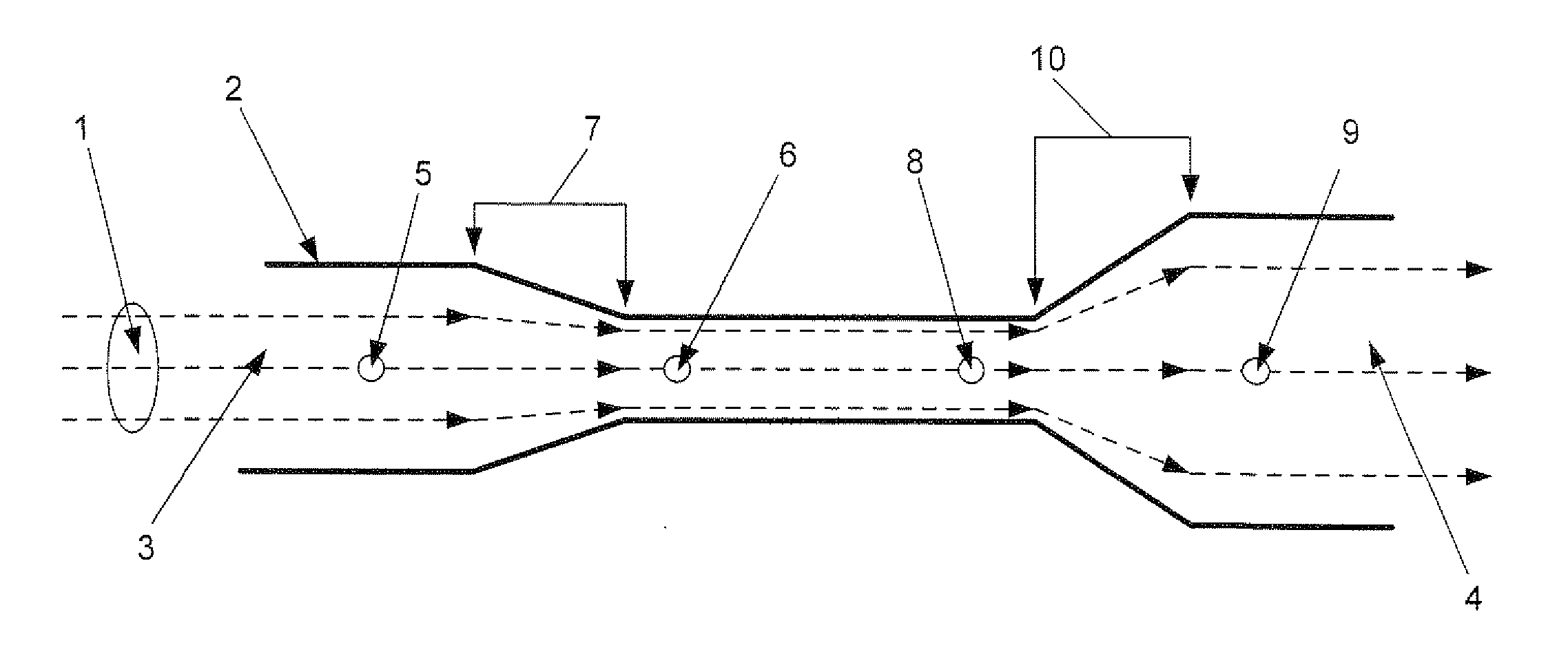
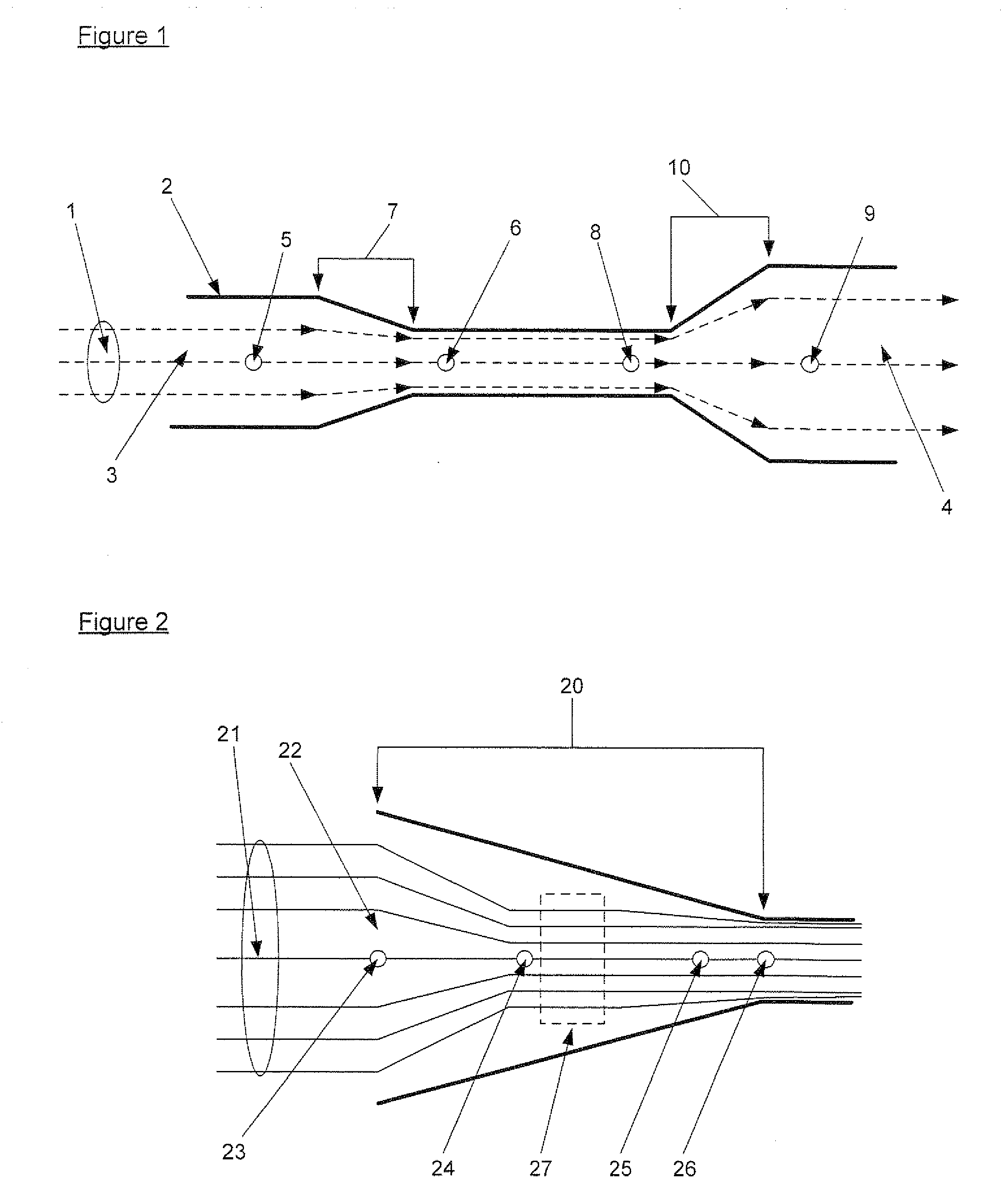
[0090]The present invention takes advantage of a number of well known principles in the fields of fluid dynamics and magnetism. Bernoulli's law is one such principle. Bernoulli states that an increase in speed of a fluid in a closed environment simultaneously results in a decrease in pressure in the fluid's potential energy. FIG. 1 illustrates this principle for a fluid 1 moving through an enclosure 2. Enclosure 2 has an inlet 3 and an outlet 4.

[0091]Assuming that fluid 1 is not compressible and the walls of enclosure 2 are not expandable; the volume of fluid leaving the enclosure through outlet 4 must equal the volume entering the enclosure through inlet 3. Thus, the sum of the kinetic and potential energy of fluid 1 remains constant throughout enclosure 2. For this to be the case, the pressure and flow speed of fluid 1 will be different at different locations within enclosure 2 in accordance with Bernoulli's law.

[0092]For example, fluid pressure at location 5 in FIG. 1 will be low...


PUM


Abstract

A supplemental power source for a building or other structure is provided. Power is generated by converting mechanical energy derived from a fluid into electrical energy. The fluid can be, for example, in the form of air in a building air duck or water in building water lines. The invention includes a specially designed turbine enclosure through which the fluid passes. The enclosure has a Venturi area which results in movement of the fluid at a rapid speed through the turbine. An electric generator with a ratable blade also is provided within the Venturi area in order to take advantage of the faster moving fluid. The faster the fluid moves, the more energy can be converted by the generator. The generator can be constructed with a plurality of electric coils and magnets which can be arranged in series / parallel combinations depending on the power requirements of a particular application.

Description

CROSS-REFERENCE TO RELATED APPLICATION[0001]This application claims priority to provisional patent application Ser. No. 61 / 096,325 filed on Sep. 12, 2008 and entitled “Micro Wind Turbine Generator Module”, the contents of which are incorporated herein by reference.BACKGROUND OF THE INVENTION[0002]The present invention generally relates to the field of energy conversion and more particularly, is directed to a method and apparatus for efficient and practical conversion of mechanical energy into electrical energy. Conversion of mechanical into electrical energy has many applications from electronic measurements and analysis to power generation. The present invention greatly advances society's goal of using all forms of energy sources, especially renewable sources, to meet the energy needs of mankind.[0003]While a preferred embodiment of the present invention will be described with reference to mechanical energy derived from wind, the invention has application to many sources of energy ...

Claims


Application Information

Patent Timeline
Patent Type & Authority Applications(United States)
IPC IPC(8): F03B13/00H02P9/04
CPCF03B13/00F03D9/00F05B2210/16Y02B10/30Y02B10/50Y02E10/72F05B2220/602F03D9/25F03D1/025F03D1/04
Inventor NYFFENEGGER, JOHANNES F.
Owner AGLOBAL TECH
Learn More