
Heat exchanger and method of producing thereof

a technology of heat exchanger and heat exchanger plate, which is applied in the direction of gas flame welding apparatus, stationary tubular conduit assembly, lighting and heating apparatus, etc., can solve the problems of affecting the integrity of plastics materials, and affecting the quality of heat exchangers

Active Publication Date: 2010-08-19
TITANX HLDG AB
View PDF15 Cites 12 Cited by
  • Summary
  • Abstract
  • Description
  • Claims
  • Application Information

AI Technical Summary

Benefits of technology

[0008]Preferably the heat exchanger has header plates which are channel-shaped with longitudinal flanges extending over and being brazed to the wide side walls. Header plates of that kind are easy to accomplish, e.g. by means of a aluminium section material, and provide accurate support for said wide side walls while brazing the parts together.
[0017]The method according to invention is an very easy one, because it comprises only two fastening steps, a first brazing one and a second welding one. This simplifies production a great deal and has the extra advantage of avoiding welding of defective brazed units, which later on would have to be to scraped after all. Further it is obvious that the method according to the invention has the extra advantage of having to fix the brazable parts only once before brazing, either by means of a fixture frame or by close fitment of the parts involved.

Problems solved by technology

This can be derived from the fact that the embodiment described has air tank cowlings made of plastics, which is not a material suitable for temperatures of such magnitude as encountered in heavy turbo- or supercharging.
Besides air tightness, coolant tightness is a main issue of heat exchangers for turbo- or supercharging of combustion engines, because coolant leakage into the air intake of a combustion engine can lead to severe engine damage.
The material mix of both sheet metal and plastics does however render even a minor water leakage repair quite difficult, because even such a minor repair causes welding heat, which could endanger the integrity of the plastics material.

Method used


Image

  • Heat exchanger and method of producing thereof
  • Heat exchanger and method of producing thereof
  • Heat exchanger and method of producing thereof

Examples


Embodiment Construction

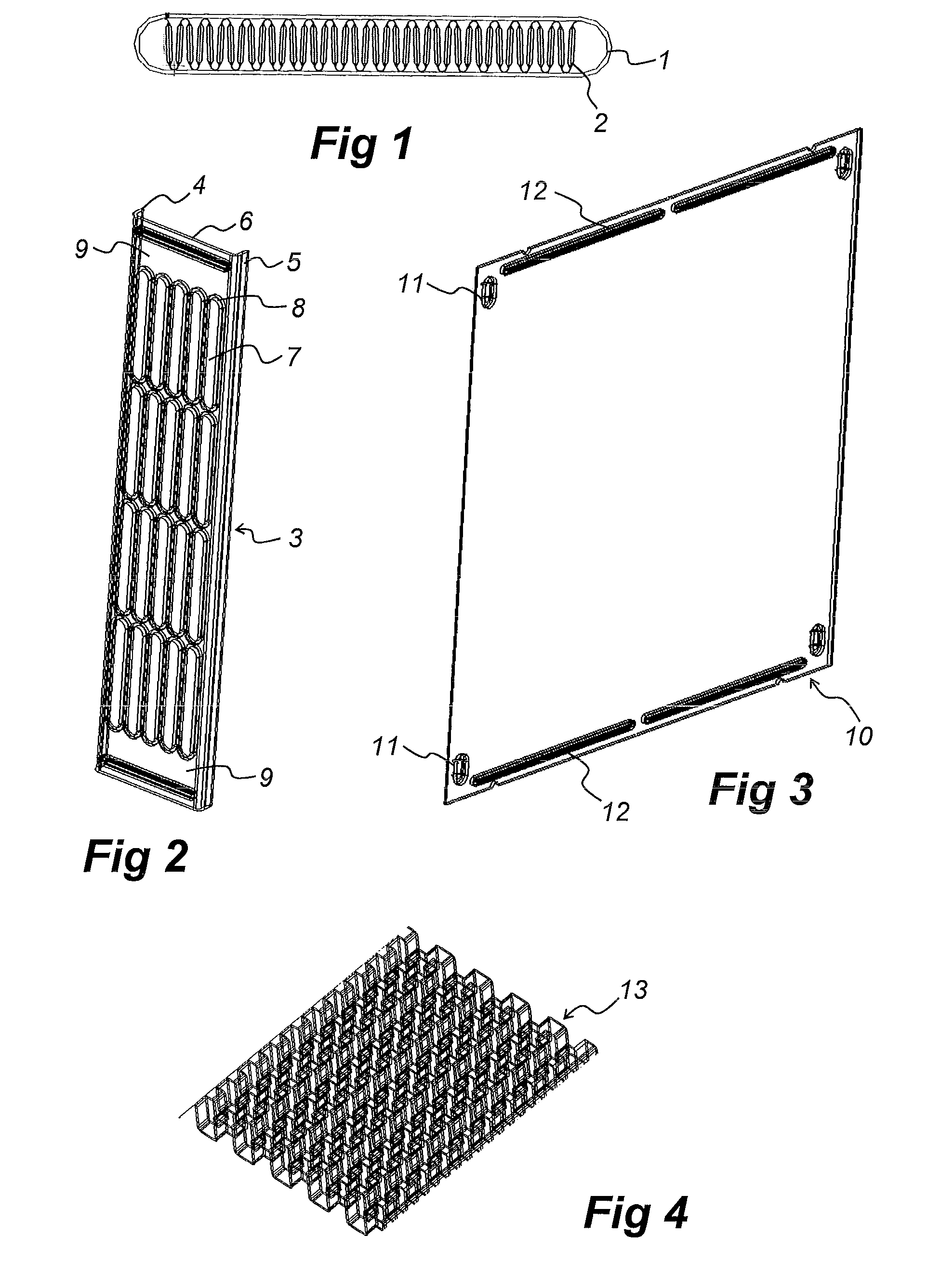
[0030]In the drawings FIG. 1 shows an air tube 1 with an internal turbulator 2 inside. The air tube 1 is made of a clad aluminium sheet in order to be brazable and has been shaped into an oblong section before being electrowelded along a longitudinal pipe seam. Inside the air tube 1 there is an internal turbulator 2, which is made of an aluminium sheet and has been corrugated lengthwise before being stuffed inside the air tube 1.

[0031]The header plate 3 shown in FIG. 2 is made of a sectional element of clad aluminium in order to be brazable too. It has two opposing flanges 4, 5 along its longitudinal edges and a flat central part 6 in-between. In the central part 6 there are stamped oblong holes 7 exactly fitting the air tubes 1. The stamping results in rims 8 protruding from the flat central part 6 in order to support the air tubes 1. The rims 8 can protrude on either side of the flat central part 6 of the header plate 3, although protrusion as shown on the side facing away from th...


PUM

PropertyMeasurementUnit
shapeaaaaaaaaaa
diameteraaaaaaaaaa
air pressure dropaaaaaaaaaa

Abstract

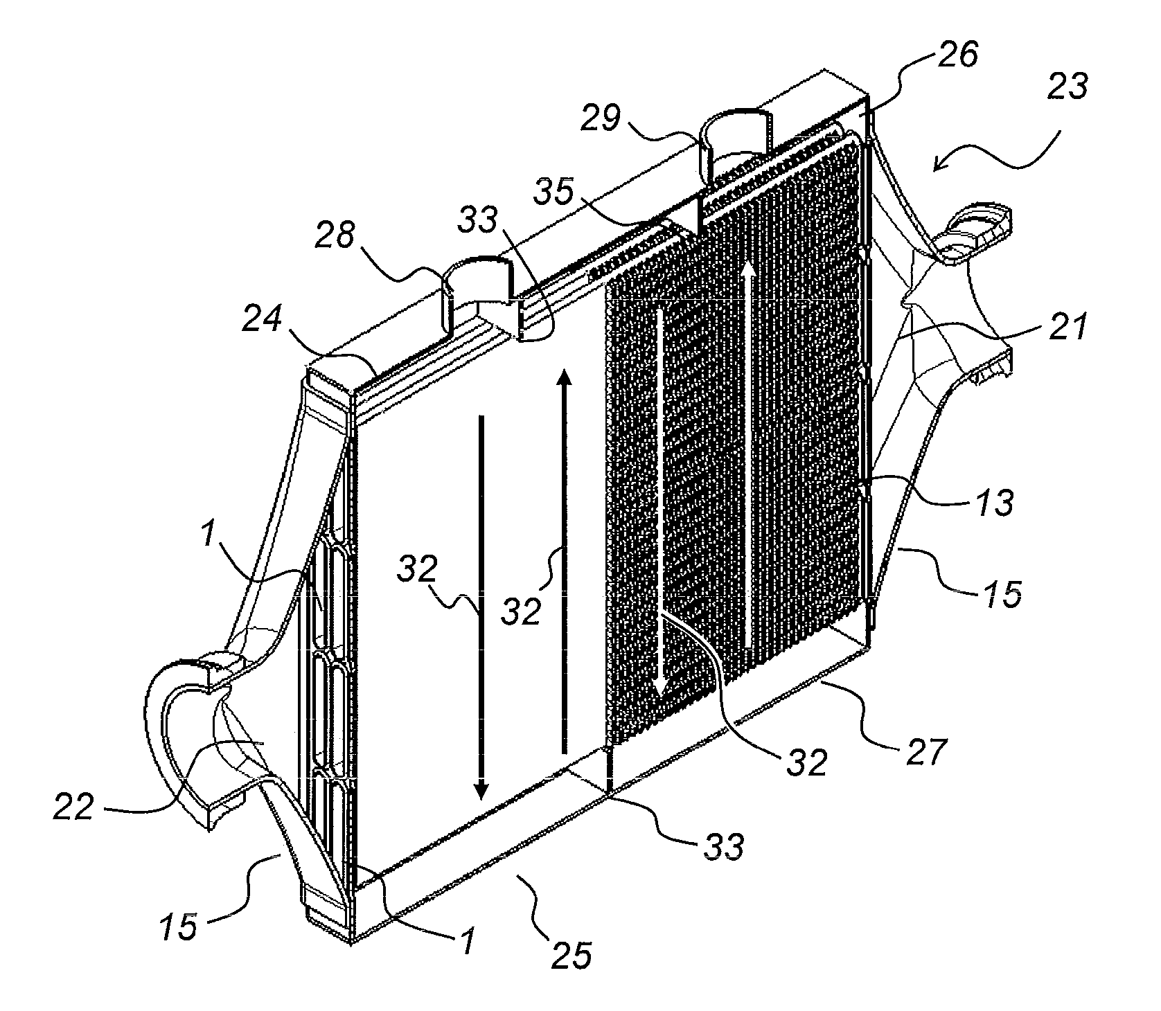
The invention concerns a heat exchanger and a method of producing thereof. The heat exchanger comprises a coolant housing with two opposing wide side walls and two header plates of an inlet air tank and an outlet air tank, respectively. The header plates are channel-shaped with longitudinal flanges extending over and being brazed to the wide side walls. Tubes extend in parallel through said housing between the two header plates, said tubes being brazed to apertures in said header plates. The coolant housing has two opposing narrow side walls tightly fitting said wide side walls and said header plates and defining together with these wide side walls and header plates a first coolant tank and a second coolant tank opposing the first one. Each air tank comprises a cowling tightly fitting and being brazed to one of said header plates each and having an air inlet and an air outlet, respectively. At least one of said two side walls is welded to said wide side walls and said header plates thus enclosing said housing.

Description

TECHNICAL FIELD[0001]The present invention relates to a heat exchanger, such as water cooled charge air cooler for a turbocharged or supercharged combustion engine, as well as to a method of producing such a heat exchanger.PRIOR ART[0002]The prior art document EP 1 707 911 A1 discloses a heat exchanger according to the introduction comprising a coolant housing having a coolant inlet and a coolant outlet, said coolant housing being of rectangular parallelepipedic shape with two opposing wide side walls and two opposing narrow side walls, the narrow side walls tightly fitting and being brazed to the wide side walls, air tubes extending in parallel through said housing between the two narrow side walls, the narrow side walls forming header plates of an inlet air tank and an outlet air tank, respectively, the air tubes tightly fitting and being brazed to apertures in said header plates.[0003]The known heat exchanger shows only a minor air pressure drop over its air tubes extending in pa...

Claims


Application Information

Patent Timeline
Patent Type & Authority Applications(United States)
IPC IPC(8): F28F9/02B23K1/008
CPCF02B29/0462F28D7/1692F28F2009/029F28F9/0209Y02T10/146F28F9/00Y02T10/12F02B23/00F28D7/0025F28F9/0224
Inventor AMAYA, LUISBIRGERSSON, BENGT-OVE
Owner TITANX HLDG AB
Learn More