
Chemical Mechanical Vapor Deposition Device for Production of Bone Substitute Material

a technology of mechanical vapor deposition and bone substitute material, which is applied in the direction of liquid/solution decomposition chemical coating, prosthesis, impression caps, etc., can solve the problems of limited availability and risky recovery procedure of autogenous bone, and the risk of viral transmission and immune reaction of allograft bone, and achieve excellent flexural, impact and tensile characteristics, excellent hydrolysis resistance, and excellent tensile properties

Active Publication Date: 2010-08-19
CHI CHARLIE W
View PDF21 Cites 4 Cited by
  • Summary
  • Abstract
  • Description
  • Claims
  • Application Information

AI Technical Summary

Benefits of technology

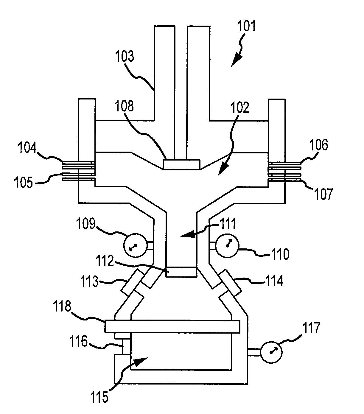
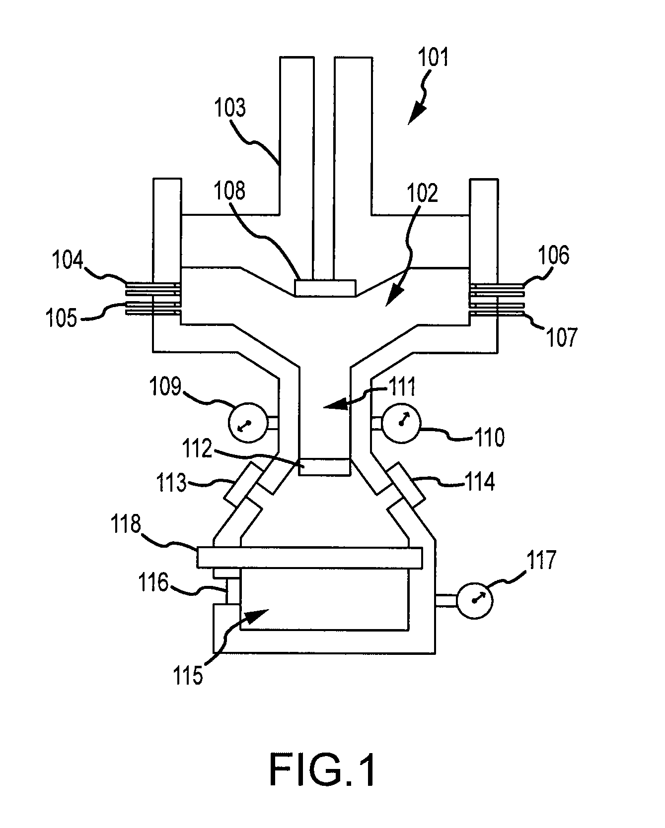
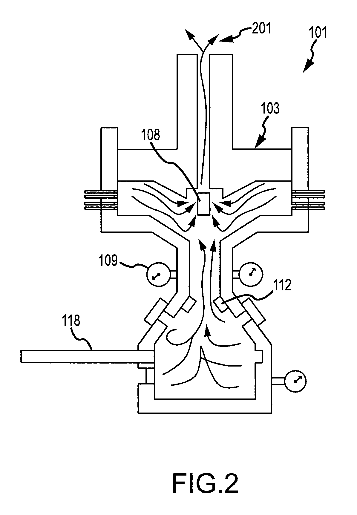
[0011]equilibrium shift to left in presence of excessive phosphate ion.The phosphorous contents of the minerals are very similar, and therefore accurate chemical analysis is required to distinguish between these minerals from changes in the solution composition during crystal growth. At high supersaturations, it is difficult to precipitate HAP alone because of the spontaneous formation of precursor phases, such as amorphous DCDP, TCP and OCP. At lower supersaturations, it has been found possible to nucleate HAP in pH conditions where the solutions are slightly under-saturated with respect to amorphous TCP and OCP. The shape growth curve can provide the process information of the percentage crystalline HAP growth on the seeds through progressive amorphous and precursor phases such as TCP, OCP and DCDP. More significantly, the ratio of crystalline to amorphous structures is closely related, not only to mechanical properties, but also to osteoconductive and osteoinductive activities during the fusion process with natural bone. The precipitates of calcium phosphate minerals in both amorphous and crystalline structures move to a final chamber and are finally deposited on the substrate surface, preferably, calcium carbonate. They are accumulated in thickness with the formation of porous structures. The pore size is determined by the solution particle size during the spraying process. More significantly, the production device presented here enables control of various ratios of amorphous to crystalline structures in calcium phosphate minerals by adjusting pressure, temperature, a solution particle size, concentration of chemicals and amount of solvent (distilled water), i.e., pH, based on the shape growth curve.
[0012]For the simulation of mechanical properties of protein, which provides elastic property and strength of natural bone, biocompatible polymer fibers, preferably, PEEK (polyetheretherketone), are added to reinforce calcium phosphate minerals during the calcium phosphate mineral deposition. Biocompatible polymers, such as PEEK, have excellent flexural, impact and tensile characteristics. Especially, PEEK is insoluble in all common solvents and, being crystalline, is extremely resistant to attack by a very wide range of organic and inorganic chemicals. It has excellent hydrolysis resistance in boiling water (autoclave sterilization) and good radiation resistance (irradiation sterilization).
[0014]The slip lines as weak interfaces can represent a degree of toughness and viscoelasticity to bone substitute material. This is an advantage using composite laminar structure. To further increase the compressive strength and rigidity of the bone substitute, thinner calcium carbonate mineral layers, compared to calcium phosphate mineral layers, can be deposited to simulate the natural bone cement slip lines. Also, in order to improve osteoinductive activities, blood vessels which nourish the tissue in natural bone (i.e., Haversian canals and Volkmann's canals) are simulated by introducing a mechanical through-hole device that allows incorporation of a finite number of through holes perpendicular or parallel to laminated directions depending on the application. These features in combination with bone morphogenetic protein (BMP) can significantly increase an osteoinductive activity. Furthermore, extracellular matrix scaffolds (ECM) can be added in combination with the polymer fibers or into transition layers (calcium carbonate layers) between the laminated calcium phosphate mineral layers. Various ECM proteins including collagen, laminin, fibronectin, and glycodaminiglcans, can be added for excellent biological scaffolds. These proteins have the advantages of supporting the migration and differentiation of osteoblastic progenitor cells, facilitate the binding of growth factors responsible for osteogenesis, and resorbing within a reasonably short period of time. At the cellular level, ECM molecules exhibit a variety of activities, including acting as a substrate for cell migration, an adhesive for cell anchorage, a ligand for ions, growth factors, and other bioactive agents. ECM molecules are ideal to form layers or substrates for cell delivery to provide high local concentrations of osteoinductive biomolecules.

Problems solved by technology

Natural bone grafts are associated with problems such as limited availability and risky recovery procedure for the autogenous bone, and risks of viral transmission and immune reaction for allograft bone from a cadaver.
However, by and large, metal, ceramic or polymer materials that have been introduced for bone substitutes have been substantially denser, heavier and significantly stiffer than natural bone although some ceramic materials exhibit similar chemical properties.
Natural bone fails gradually when stressed under high compression.
By contrast, bone substitute ceramic materials commonly show sudden and catastrophic failure under compression, because most of the bone substitute materials individually lack the several areas of biomechanical properties of natural bone, such as elasticity, viscoelasticity and lamellar structural properties.

Method used


Image

  • Chemical Mechanical Vapor Deposition Device for Production of Bone Substitute Material
  • Chemical Mechanical Vapor Deposition Device for Production of Bone Substitute Material
  • Chemical Mechanical Vapor Deposition Device for Production of Bone Substitute Material

Examples


Embodiment Construction

[0034]The invention provides production of a bone substitute material using chemical solution spray deposition (CSSD) and isostatic press processes with reinforced plastic fibers, preferably PEEK, resulting in bone substitute having composite laminated structures with controlled porosity. In order to increase toughness and elastic behavior of bone substitute material comparable to natural bone, the composite laminar structure is introduced with reinforced polymer fibers. In order for bone substitute material to have high compressive strength in load bearing applications, calcium phosphate mineral is deposited and forms a layer with an option of inclusion of calcium carbonate mineral into the calcium phosphate mineral. Another option is that calcium carbonate forms one or more separate thin layers between the calcium phosphate layers. The high compressive strength of calcium carbonate material compared to calcium phosphate can provide additional rigidity of the bone substitute materi...


PUM

PropertyMeasurementUnit
diameteraaaaaaaaaa
temperatureaaaaaaaaaa
biocompatibleaaaaaaaaaa

Abstract

A method for fabricating a substitute component for bone, including the processes of: provision of a chemical spray including at least three of calcium chloride, hydrogen phosphate, hydrogen carbonate and water to form a combined solution; reaction and precipitation of the combined solution onto a substrate; allowing the precipitated particles to form a porous structure on the substrate; applying substantially isostatic pressure to the porous structure to form a compressed structure; and (optional) providing one or more through-holes in the compressed structure to promote osteoinduction.

Description

CROSS REFERENCE TO RELATED APPLICATIONS[0001]This application is a continuation application of and claims priority under 35 U.S.C. §120 to U.S. patent application Ser. No. 11 / 212,977, now U.S. Pat. No. 7,687,098, entitled Chemical Mechanical Vapor Deposition Device for Production of Bone Substitute Material, filed Aug. 26, 2005, and which is hereby incorporated by reference in its entirety as though fully set forth herein.[0002]This application is also related to co-pending U.S. patent application Ser. No. 12 / 708,438, entitled Chemical Mechanical Vapor Deposition Device for Production of Bone Substitute Material, filed on Feb. 18, 2010, and which is hereby incorporated by reference in its entirety as though fully set forth herein.FIELD OF THE INVENTION[0003]This invention relates to production of calcium phosphate mineral-based bone substitute material using a chemical solution spray deposition device that accommodates porous and composite laminar structures with reinforced biocompa...

Claims


Application Information

Patent Timeline
Patent Type & Authority Applications(United States)
IPC IPC(8): C23C16/00A61K6/838
CPCA61F2/28A61F2/3094A61F2/30965A61F2002/30784A61F2002/30971Y10T428/254A61F2310/00293C23C18/1204C23C18/1245Y10T428/25A61F2002/30986A61P19/00A61P43/00
Inventor CHI, CHARLES
Owner CHI CHARLIE W
Learn More